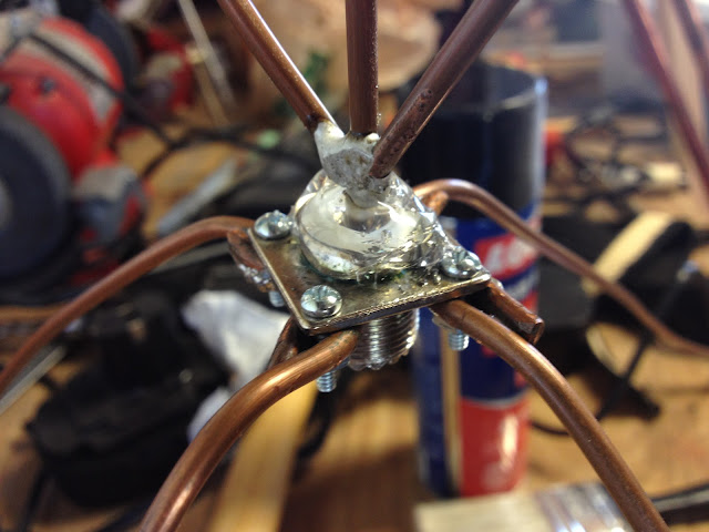
Of course, since I had a scanner, I needed an antenna. I'm just getting into the whole scanner thing, so I didn't want to spend too much on the antenna since I didn't pay much for the scanner (which is several years old). One of the cheapest and easiest antennas to build is the quarter-wave ground plane. I had some #8 ground wire laying around, as well as an SO-239 connector, so I was off to the races.
There are several good calculators out there to help get the proper dimensions, however, the math is fairly simple:
468 divided by Frequency in MHz gives you the half-wave element length in feet.
The quotient from above divided by 2 gives you the quarter-wave element length in feet.
Take the quotient from the last problem and multiply it by 12, the product is the length of element in inches.
For example, if you want an antenna for the middle of the 2m ham band:
(468/146) / 2 x 12 = 19.23" which roughly equals 19 1/4" (since tape measures are in fractions of an inch).
It helps if you cut it a little long to allow you to tune to your specific location. I actually cut mine for resonance on the public services band (~150MHz) since that is what is in use in my area, however, I get acceptable performance on the 2m band as well (about 1.7:1 VSWR).
Bending the ground plane elements down to 45 degrees brings the resistance of the antenna closer to 50 Ohms. I'm not sure how this works exactly, maybe someone could drop a post and let me know why this works.
Here is a quick pic of the completed antenna. The ground plane elements sag a bit with they are supporting the weight of the antenna. They are straight when the antenna is suspended properly.
I also added vertical stubs for the 440MHz band as well as the 800MHz bands. I didn't add ground plane elements for them as I'm not sure that I would see any benefit from doing so since I have the 2m elements. Here is a close up of the verticals.
The last thing that I did was to seal the top of the connector with some silicone caulking. This will help to keep water out of the coax, which would degrade the metal over time. I would have used coax-seal, but I ran out and didn't feel like spending the money on this antenna.
And the final thing that I need to do, as you can tell from the background of the picture above, is clean my work bench! It is getting crazy in there, so hopefully I can get that squared away soon.
My Parts List:
- 1 x SO-239 connector
- 8' of #8 grounding wire
- 4 x little screws
- Caulking
Time to Completion:
- About one hour for this one, mainly getting the jig built to solder the pieces together.
Next time I'll work on getting better pictures. I tend to feel my way through some of these projects and don't think to document as I fumble along.
73,
Richard, KK4JDO


One thing that I guess that I should mention is that I now use this for 2m APRS since I have moved my scanner into my truck. It will get moved back to scanning duties when I figure out what scanner I want to buy for the house. I want something with a lot of features as well as PC control, but I don't want to pay what those feature cost. It's rough being a cheap-skate. ;-)
ReplyDelete