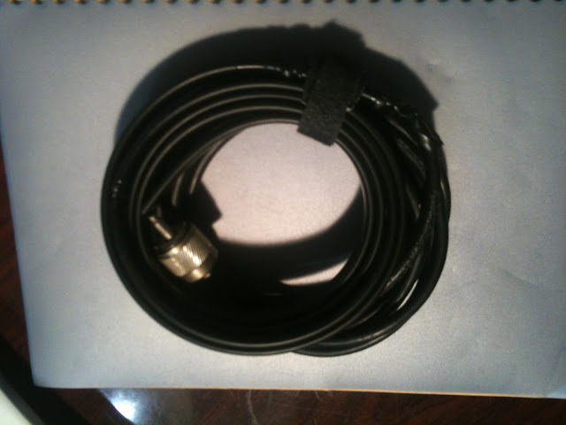
Sunday, June 24, 2012

Update to the PTT Mic via USB Project

So since I've gotten into trying to learn Morse code, I needed some type of oscillator, so that I can hear my key as I practice.  You can purchase an oscillator from companies like MFJ, or you can make the on the cheap with a piezoelectric buzzer and a 9v battery.  I chose a slightly different route.

My option was to add a 1/4" jack to my PTT desk mic via USB project box.  I did keep the piezo buzzer in case I wanted to practice without interacting with the PC, but I am currently using a program called MorseRabbit, which can accept input from the keyboard spacebar.  Only, in this instance, the input is coming from my straight key, which in turn is connected to the Teensy USB microcontroller, which is emulating a keyboard.

My Parts List:

  • 1/4" mono audio jack (panel mount)
  • 5v piezo buzzer
  • bit of wire and solder
Time to Completion:
  • 30 minutes, including adding the necessary code to the "sketch"
Here is a pic:


Here is a copy of the code "sketch" that I am using:

#include <Bounce.h>

Bounce button0 = Bounce(0, 10);
Bounce button1 = Bounce(1, 10);

void setup() {
  pinMode(0, INPUT_PULLUP);
  pinMode(1, INPUT_PULLUP);
  pinMode(12, OUTPUT);
  pinMode(14, OUTPUT);
}

void loop() {
  // Update all the buttons.  There should not be any long
  // delays in loop(), so this runs repetitively at a rate
  // faster than the buttons could be pressed and released.
  button0.update();
  button1.update();

if (button0.fallingEdge()) {
   // press and release CTRL
   Keyboard.set_key1(KEYPAD_PLUS);
   Keyboard.send_now();
   Keyboard.set_key1(0);
   Keyboard.send_now();
   analogWrite(12, 200);
  }

 if (button0.risingEdge()) {
   // press and release CTRL
   Keyboard.set_key1(KEYPAD_PLUS);
   Keyboard.send_now();
   Keyboard.set_key1(0);
   Keyboard.send_now();
   analogWrite(12, 0);
  }
  
if (button1.fallingEdge()) {
   // press and hold space
   Keyboard.set_key1(KEY_SPACE);
   Keyboard.send_now();
   analogWrite(12, 200);
   //analogWrite(14, 255);
  }

 if (button1.risingEdge()) {
   // release space
   Keyboard.set_key1(KEY_SPACE);
   Keyboard.set_key1(0);
   Keyboard.send_now();
   analogWrite(12, 0);
   //analogWrite(14, 0);
  }  
}


You have to forgive the sloppy wiring, it was too much hassle for this project to etch a pc board.  Now I have the ability to practice CW on my PC, both sending and copying!

73,

Richard, KK4JDO


Thursday, June 21, 2012

CW aka Morse Code

So, I want to venture into the land of CW and become a true ham.  When I first attempted getting into Amateur Radio over 20 years ago, in order to gain Novice privileges, you had to demonstrate proficiency in receiving (copying) Morse Code at five words per minute.  This turned out to be my biggest challenge, and the reason that I didn't earn my license back in the late 80s.  Fast forward to today, and I still want to master this.  So, I went to my local ham shop and picked up a straight key, which of course needs to be mounted on something so that it doesn't move all over while you are trying to use it.  This lead to a small project, and the topic of today's post.  This is a quick and easy project, and didn't cost much.  I went to Home Depot to see what I could find, figuring that a block of wood would work.  Well, I found that, and then something even better.  A chunk of base molding was the exact right size, and cost around a buck.  A quick coat of paint, and two screws later, and I had a functional straight key.  Now all I need to do it learn to use it!

My Parts List:

  • 1 x Chunk of base molding
  • 1 x Straight Key
  • 2 x Wood Screws
  • 1 x Some old spray paint.  ;-)


Time to Completion:


  • It only took a few minutes to mount the key once the paint dried, and only a few minutes to paint it.  The longest part was waiting for the paint to dry!


Here is a pic:


All in all, a simple, fun little project that hopefully will open up a whole new world for me!

73,

Richard, KK4JDO

Sunday, June 17, 2012

Fun Project with the Kids

Here is a fun little project to do with kids.  It is also educational.  This was done a few years ago, but we still have fun with it from time to time.  This is a simple electro-magnet built by winding some copper wire around a steel screw, and connecting it to an electrical current (low voltage provided by some "AA" batteries) via an on/off switch.  I stuck a little LED in there to show when it was turned on, not that it was needed with a switch that was labeled, but it was fun.

My Parts List:

  • 1 x Project Box
  • 1 x 6' of copper wire
  • 1 x Screw
  • 1 x SPST switch
  • 1 x LED (with resistor built in)
  • 1 x power connecter (really not needed, batteries could be inside of project box)


Time to Completion:

  • About four hours with the "help" from the kids.  ;-)


Here is a pic:


Just a fun little project.  I'll work on getting some pictures of it in use.

Thanks,

Richard, KK4JDO

Mic Adapter

I was recently in a position where I had a 2m radio that needed a new mic.  Specifically, I have a Yaesu FT-2200 that I picked up from eBay on the cheap.  This supposedly perfectly working radio had a myriad of issues, one of which being a mic with two bad capacitors.  One solution was to go purchase a new mic.  Well, this is an older radio, so they don't make mics specifically for this rig any longer.  However, I was able to find a suitable replacement, the only down side being that said replacement cost almost as much as I paid for the radio!  That wasn't gonna happen.  Another option was to rewire a mic that I already own to use with this radio.  The downside was that I actively use both mics, one for my Kenwood TS-440S, and the other (wired for the Kenwood), I use via my USB PTT box with EchoLink.  So I didn't really want to rewire either of those.

The final solution was a mic adapter!  It was a little aggravating to build as I had to cross between two vendors that do things slightly different (Kenwood uses two grounds, one for the mic, one for the PTT, while Yaesu uses a single common ground).  But it wasn't really all that bad, and seems to work.  Now I just need to get my Moxon mounted where I can use it, and I can talk on my preferred repeater without being all scratchy!

My Parts List:

  • 1 x 8-pin female mic connector
  • 1 x 8-pin male mic connector
  • 1 x 1' length of mic cable (initially I used Cat-5e, which worked good also)
  • 1 x 3" length of 1/2" PVC
  • 1 x 1/2" PVC cap


Time to Completion:

  • It took around 30 minutes to make, including scrounging the PVC to hold the male side of the connection since I didn't have a non-chassis mount connector handy.


Here is a pic:


This was an easy project that was a quick fix for a problem, and certainly cheaper than buying a new mic!

73,

Richard, KK4JDO

Tuesday, June 12, 2012

Intermod and Spurious Emissions!

So, as I was scanning the 10m band, I noticed that I was receiving occasional bursts of static on my 2m radio.  These were occurring as I crossed fairly strong carriers, which means that these carriers were interacting with my rig in receive mode, and causing what is called intermodulation, which was resulting in a spurious emission.

Here are some links for more reading on these phenomena: 


I recorded a quick video of it to show folks that just because you are using a receiver, it does NOT mean that you are not also broadcasting a signal!  Something to be mindful of, especially if you are in an area that is sensitive to RF fields (thinking of mining sites that use an RF signal to detonate explosives, among other scenarios).


I should probably point out that the volume on the radio that I am adjusting is completely down, the only radio that has its volume turned up is my Yaesu FT-2200 2m radio.  The sounds that you are hearing are the spurious emissions generated by my TS-440S tuned to ~28.5MHz being received by my FT-2200 on 147.120MHz.  I should also point out that these are extremely localized and can not be picked up beyond my shack.  I tried with an HT in the yard under the dipole and got nothing.  Also, I apologize for the poor quality of the video, I shot it with my iPhone 3GS, which has a pretty lousy camera.

73,

Richard, KK4JDO

Using a PTT desk mic on a PC

So in this post, I'm going to talk about a cool project that I finished a few weeks ago.  I like to use EchoLink (http://www.echolink.org/) to chat with people all over the world.  One of the uses for EchoLink, and the only thing that I use it for, is to connect to a repeater that you are too far away to hit using RF alone.  This software connects you to that repeater, and broadcasts what you say into your PC mic as if you were using a radio.  That being said, I like to feel like I am talking into a real rig, instead of talking on Skype or some other VoIP application when I am using EchoLink, especially since it is only accessible by other licensed Hams.  To that end, I had an old mic laying around, so I decided to connect it to the computer.  There were several obstacles that needed to be surmounted, the first being that the mic used an 8-pin connector for Kenwood HF radios, and the second being that you needed the press the PTT (Push-To-Talk) button in order for your audio to be sent out of the mic's audio pins.  The final issue was that the EchoLink software needs to be "keyed" as well by pushing down the space bar on your PC.  Here is how I solved these issues:

To convert from 8-pin to something that the PC could accept, I wired up the audio pins from an 8-pin male connector (the mic has a female, although it seems as though the names should be reversed) to an 1/8" female audio jack.  I mounted both in a small project box to make the assemblage a little easier to use.  This took care of getting the audio into the PC, but I still had to hit the space bar to "key" EchoLink, and at the same time hit the PTT button on the mic to connect the mic element to the audio pins inside the mic.  This was annoying to say the least.  Enter the Teensy USB Development Board:


This board connects to the PC and is recognized as one of several devices, a keyboard, a flash device, a MIDI device, etc.  The main one that I am concerned with was the ability to emulate a USB keyboard.  I soldered a connection from the PTT pins in the mic jack to one of the digital pins on the Teensy board, and another one to the ground pin.  This allows me to detect when the PTT button is depressed on the mic.  I then took this detection, and triggered a key press event to key EchoLink!  Now I can use EchoLink just like a normal radio, via the desk mic, without keyboard input.  Just for fun, I added a red LED to know when the mic PTT key is depressed (to hopefully avoid "hot-mic" issues).

My Parts List:

  • 1 x Teensy USB Board ( http://www.pjrc.com/teensy/)
  • 1 x Project Box
  • 1 x 8-pin male mic connector
  • 1 x 1/8" (3.5mm) audio connector
  • 1 x Red LED
  • 1 x 220-Ohm resistor


Time to Completion:

  • About four hours including figuring out the code for the "sketch" on the Teensy board.


Here is the simple schematic:


Here are a few pics:


Here is the code that I used on the Teensy board (which uses the Arduino IDE environment):


#include <Bounce.h>


Bounce button0 = Bounce(0, 10);


void setup() {
  pinMode(0, INPUT_PULLUP);
   pinMode(12, OUTPUT);
}


void loop() {
  // Update all the buttons.  There should not be any long
  // delays in loop(), so this runs repetitively at a rate
  // faster than the buttons could be pressed and released.
  button0.update();


if (button0.fallingEdge()) {
   // press and release CTRL
   Keyboard.set_key1(KEYPAD_PLUS);
   Keyboard.send_now();
   Keyboard.set_key1(0);
   Keyboard.send_now();
   analogWrite(12, 200);
  }


 if (button0.risingEdge()) {
   // press and release CTRL
   Keyboard.set_key1(KEYPAD_PLUS);
   Keyboard.send_now();
   Keyboard.set_key1(0);
   Keyboard.send_now();
   analogWrite(12, 0);
  }
}

Well, that's all for this post, I hope that you have enjoyed it, I certainly enjoyed making it!

73,

Richard, KK4JDO

QSL?!

So, what it's all about..  Since I just had two brief but nice 10m QSO's, I thought that I'd post a quick pic of the two QSL cards that I have received thus far in my month long period of being a ham.  Not a project, but still cool in and of itself.


The top card is from my very first Ham QSO with a gentleman in California, and the second is from a fellow ham in Montana.  QSL cards are a neat way to acknowledge that a QSO (conversation) has occurred, and act as a memory tickle to remind you of it.

73,

Richard, KK4JDO

Monday, June 11, 2012

The Obligatory Shack Pic

So now I can show you what all of those antenna are used with!  This is a quick overall shot of my "shack" as it stands right now.  I am considering some upgrade options in the near future, so stay tuned to see what kind of rig takes center stage (thinking TS-2000 for the shack and IC-7000 or FT-857D for the truck).


Included in this pic are:

Kenwood TS-440S, 20 years old and still talking around the world!  (just talked to Russia and Ukraine!)
Yaesu FT-2200 (look for an upcoming post on lessons learned about eBay)
MFJ-941D Antenna Tuner
Heath 3A power supply for testing purposes
Kenwood PS-30 for powering the TS-440S
SignaLink USB for APRS and other digital modes (trying to talk to the ISS, but need higher gain antenna)
Wouxun UV3D HT
Kenwood TS-120S (not feeling so well these days)
Homebrew PTT Mic to USB adapter to allow me to use my desk-mic with EchoLink (look for a future post)
Shure 256T desk mic
Kenwood MC-50 desk mic
El-cheapo CW straight-key (again, look for an upcoming post)
Radio Shack SWR/Power meter


Here are some more pics:


So that sums up my current shack.  More details as things change!

73,

Richard, KK4JDO

Last antenna post for now... ;-)

Okay, last one for now.  So the j-pole works pretty well, but I was still staticy when transmitting.  What I needed was a directional antenna for maximum gain.  Again, purchasing one at the Candy Store would have been $50 or more.  But for less than $8 at Home Depot, I was off and running.  When I use this antenna, I am full-quieting on the repeater.  The downside for me right now is that I cannot permanently mount this one outside, as I need to be in the front of the house to point at the repeater that I like to use (147.120MHz,+600,PL-103.5).

My Parts List:


  • 10' of 8AWG copper wire (enough for about three antenna like this, I want to make one for 70cm also)
  • 10' of 3/4 PVC pipe (again, enough for multiple antenna)
  • 50' of RG-58 coax


Time to Completion:


  • About four hours


Here is a pic:


More information on this type of antenna can be found at:

http://www.moxonantennaproject.com/

I have to say that I am impressed with how well this antenna functions!  The one thing that I do need to add is a balun at the feed-point, that is on the project list!  ;-)

73,

Richard, KK4JDO

And another antenna!

Alright, this is almost the last one for now, I promise.  I needed something to get better reception on my little handheld Wouxun HT, but didn't feel like spending $25 or so for one from the local ham store (referred to by other hams as the Candy Store).  My solution was to build a roll-up j-pole antenna out of left-over twinlead from my dipole.  Again, before I was not able to use my HT from home as the repeater is clear across town from where I live, and 5W wasn't going to cut it with the little rubber-duck that came with the HT.

My Parts List:


  • 6' of 300-Ohm twinlead
  • 10' of RG-58 coax with a PL-259
  • 1 PL-259 to Reverse-SMA adapter (had to buy this one, too much of a pain to make it)


Time to Completion:


  • 30 minutes or so


Here is a pic:


So admittedly I need a better pic of this one.  I'll work on that...

73,

Richard, KK4JDO

Another antenna! 2m mobile for home use

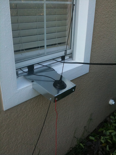
So I had my HF antenna built, but I needed something for VHF and UHF so that I could participate in local nets on my repeater without sitting in my truck all night.  However, I live (for now) in a community with a restrictive HOA.  My solution was the same as with my dipole, hide it behind my house.  The quickest option was to purchase a small magnet mount antenna, but those require something metallic to attach the magnet to.  This also serves as a groundplane to help with the RF gain of the antenna.  My solution was to get a sheet of galvanized metal from my local Home Depot, and with a quick use of my tin-snips and some self-tapping screws, build a small shelf for the mag mount antenna to sit on.  However, this didn't give quite enough of a metallic surface to act as a groundplane, so I added what is called a counterpoise to the shelf to help with having a sufficient groundplane to allow the antenna to function with as much efficiency as possible.

My Parts List:


  • 1 sheet of galvanized sheet metal
  • 20" of 12AWG stranded wire


Time to Completion:


  • One hour or so.


Here is a pic:


I need to add a piece of 2x4 inside of the box part to make it a bit stiffer, but it works well as it is.  One note of interest, before I added the counterpoise, I was not able to hit the repeater that I prefer to frequent, after adding it, I am able to make contact.  Proper RF grounding is important!

73, 

Richard, KK4JDO

You'll have to pardon all of the posts right at first, I have a back-log since I'm just starting this blog.  When it comes to me and blogs, that what you can get while you can, I tend to forget them after a while...  ;-)

73,

Richard, KK4JDO

First Antenna, 1/2 wavelength 10m dipole

Hi All,

So, since this is about Ham Radio, you had to have guessed that there would be talk about various types of antenna.  I have a terrible dislike of spending money, so instead of buying my first antenna, I decided to build one instead.

As a newly minted Technician class Ham Radio Operator, the only HF bands that you have voice privileges on is the 10-meter band (28.3MHz - 28.5MHz).  You can operate CW on a few lower bands, but since I am still in the process of learning Morse Code  (CW), I decided to build an antenna for use where I can talk on voice (using what is called SSB or Single Side Band).

A dipole is a very basic antenna, and very easy to build.  Basically, you need some wire, and something to use as a feedline, such as coax or twinlead.

My Parts List:


  • 20' of stranded copper wire
  • 1 x 3/4" PVC "T" fitting
  • 2 x 2" pieces of 3/4" PVC pic as insulators
  • 20' of nylon rope
  • 100' of 300-Ohm twinlead from Radio Shack


Time to Completion:


  • One hour to measure, cut, solder, mess-up, re-do, and finish.
  • One additional hour to hang between two trees.


Here is a quick pic:


Once it was up in the air, I connected it to my radio via my tuner, and was talking to California, Idaho, Montana using SSB on 28.4MHz!

That it for this post, hope you enjoyed it!

73,

Richard, KK4JDO

Greetings and Salutations!

Hello to anyone that happens by.  Not sure how you ended up here, but welcome!

The main goal of this blog is to catalog the various projects that I am working on, Ham Radio related or otherwise.  Well, with that being said, I'll dive into some project related posts.

73,

Richard, KK4JDO