Showing posts with label antenna. Show all posts

Tuesday, September 17, 2013

Behold the awesomeness that is to be my 160m dipole...

This is a paraphrase/enhancement of a cross-post that I made to Reddit.  I'm putting up a ladder-line fed 160m dipole in the near future.  I forgot the insulators when taking the picture...


I should be able to get it up to around 60' in the trees that I have available. It won't be perfectly straight so it will favor the southeast a bit (watch out Caribbean, I'm coming for you!), but it should be better than what I have right now. Here is the planned layout as of right now.


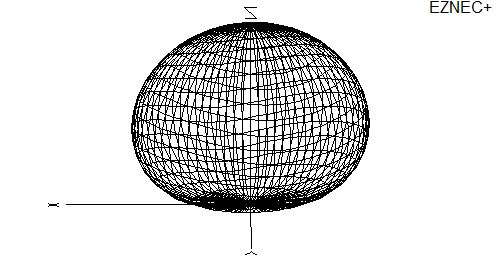
After working it out in EZNEC it doesn't look as if the slight jog will throw off the pattern that much. It's still basically an NVIS antenna at the design frequency. Or to say it another way, I don't have any 260' trees to make it act like it would at a half-wave up.


At 1.8MHz it is definitely an NVIS antenna:


At 3.8MHz it is starting to look a little better, but kinda looks like a tumor (this is the favoring of the SE that I mentioned above):


At 7.2MHz it is starting to look more like a traditional dipole over real ground:

Once you get up to 14.2MHz you start seeing some weirdness:


To be honest, the main goal is for this to be a multiband doublet that just happens to be cut for 160m. I'm okay with NVIS on 160 for now. If I really start getting into it I might try an inverted-L or a vertical at some point in the future.  Several Redditors made that suggestion.

Total cost of the antenna is:

$47 for the wire at Home Depot
$50 for the spreaders and center support
$24 for the dacron rope at tractor supply
$06 for the insulators
$127 total

And I have enough wire left for a 40m end fed half wave for my Rockmite-40 with enough rope for hanging that as well. So I guess it was basically $127 for two antennas (plus the xformer parts for the efhw).  Not too shabby as one comment that I got so eloquently put it!  ;-)

73,

Richard, KK4JDO

Sunday, May 12, 2013

EZNEC Antenna modeling software

Hi All,

I have come to really appreciate that antenna modeling software called EZNEC.  It is a great front-end for NEC and is fairly simple to learn and understand.  However, this post isn't about reviewing the software, I think that it speaks for itself.  The one downside to EZNEC is that the Pro version is really expensive for an individual to purchase, but that is the version that has handy features like a tool for creating grids, which are necessary if you want to model a flat surface.

Being essentially a fairly cheap person, I decided to write a PERL script to do this instead of ponying up for the Pro version (I did purchase the Plus version at $139 though).  Since the ham radio community is a great group of folks (excepting a small few, I may post about that in the future), I wanted to give a little something back.  So, if you need to create a grid and don't want to do it manually, here you go!

This software is still a little bit of a work in progress, so expect some updates to this, but it is pretty well ready to go at this point.  Future additions will include the ability to model a hemisphere and a parabola for modeling dish antennas.

So without further adieu, here is the form.  Just click "Submit" after filling it in and you will get back a block of text that can be copied and pasted into a text document for import into EZNEC.  Detailed instructions on the import procedure are beyond the scope of this post, but they are easily accessible in the software itself which has an awesome help file system.


I hope that you can make use of this! I enjoyed scripting it and hope to be able to continue to update it. Please leave a comment if you like it our would like to suggest improvements or request features.

Once imported, the grid will look something like this, depending on the options that you chose.


One side note, I am a network engineer by trade, not a programmer or web designer.  I use PERL for my job, but an not elegant.  I tend to be a brute force developer.  The code is ugly, but it works, which is usually what happens to PERL scripts over time, I just start out that way and save all the intervening effort.  ;-)

Thanks and 73,

Richard, KK4JDO

Saturday, November 3, 2012

Quarter Wave Ground-Plane Scanner Antenna (and 2m ham antenna)

One of the purchases that I got via eBay is a Radio Shack PRO-2050 police/fire/etc scanner.  I've never had a scanner before, and this was a cheap way to check it out.  I didn't get a pick of it before I ended up moving it from the shack to the truck, so I nabbed a picture of the internet.  Here is what my scanner looks like for those that haven't seen one:


Of course, since I had a scanner, I needed an antenna.  I'm just getting into the whole scanner thing, so I didn't want to spend too much on the antenna since I didn't pay much for the scanner (which is several years old).  One of the cheapest and easiest antennas to build is the quarter-wave ground plane.  I had some #8 ground wire laying around, as well as an SO-239 connector, so I was off to the races.

There are several good calculators out there to help get the proper dimensions, however, the math is fairly simple:

468 divided by Frequency in MHz gives you the half-wave element length in feet.
The quotient from above divided by 2 gives you the quarter-wave element length in feet.
Take the quotient from the last problem and multiply it by 12, the product is the length of element in inches.

For example, if you want an antenna for the middle of the 2m ham band: 

(468/146) / 2 x 12 = 19.23" which roughly equals 19 1/4" (since tape measures are in fractions of an inch).

It helps if you cut it a little long to allow you to tune to your specific location.  I actually cut mine for resonance on the public services band (~150MHz) since that is what is in use in my area, however, I get acceptable performance on the 2m band as well (about 1.7:1 VSWR).

Bending the ground plane elements down to 45 degrees brings the resistance of the antenna closer to 50 Ohms.  I'm not sure how this works exactly, maybe someone could drop a post and let me know why this works.

Here is a quick pic of the completed antenna.  The ground plane elements sag a bit with they are supporting the weight of the antenna.  They are straight when the antenna is suspended properly.


I also added vertical stubs for the 440MHz band as well as the 800MHz bands.  I didn't add ground plane elements for them as I'm not sure that I would see any benefit from doing so since I have the 2m elements.  Here is a close up of the verticals.


The last thing that I did was to seal the top of the connector with some silicone caulking.  This will help to keep water out of the coax, which would degrade the metal over time.  I would have used coax-seal, but I ran out and didn't feel like spending the money on this antenna.


And the final thing that I need to do, as you can tell from the background of the picture above, is clean my work bench!  It is getting crazy in there, so hopefully I can get that squared away soon.

My Parts List:

  • 1 x SO-239 connector
  • 8' of #8 grounding wire
  • 4 x little screws
  • Caulking
Time to Completion:
  • About one hour for this one, mainly getting the jig built to solder the pieces together.

Next time I'll work on getting better pictures.  I tend to feel my way through some of these projects and don't think to document as I fumble along.

73,

Richard, KK4JDO

Monday, June 11, 2012

Last antenna post for now... ;-)

Okay, last one for now.  So the j-pole works pretty well, but I was still staticy when transmitting.  What I needed was a directional antenna for maximum gain.  Again, purchasing one at the Candy Store would have been $50 or more.  But for less than $8 at Home Depot, I was off and running.  When I use this antenna, I am full-quieting on the repeater.  The downside for me right now is that I cannot permanently mount this one outside, as I need to be in the front of the house to point at the repeater that I like to use (147.120MHz,+600,PL-103.5).

My Parts List:


  • 10' of 8AWG copper wire (enough for about three antenna like this, I want to make one for 70cm also)
  • 10' of 3/4 PVC pipe (again, enough for multiple antenna)
  • 50' of RG-58 coax


Time to Completion:


  • About four hours


Here is a pic:


More information on this type of antenna can be found at:

http://www.moxonantennaproject.com/

I have to say that I am impressed with how well this antenna functions!  The one thing that I do need to add is a balun at the feed-point, that is on the project list!  ;-)

73,

Richard, KK4JDO