Showing posts with label communications. Show all posts

Wednesday, December 4, 2013

KF5INZ "Easy Digi" Build

Today's post is to cover the quick build of the KF5INZ "Easy Digi" Sound Card Interface.  This was a great little kit.  I can't find the parts separately for what this kit costs.  I can't stress enough what a great value it is at $11 shipped.  The pcb is good quality and the instructions are almost unnecessary it is so easy to assemble.  I think that it took me a total of 15 minutes from opening the package to having a completed board.  I still need to build a box for it, but the board itself was done in just a really short amount of time.

On to the pictures...

The kit came in a typical little yellow envelope, with the parts and pcb in a little zip-lock bag.


The parts are all easy to identify and can be sorted in seconds.

Here is the optoisolator IC and diodes installed .  The polarity of the diode is silk-screened on the board.

Then the resistors.

Then onto the capacitors, all two of them...

And finally the audio transformers.  Quick and easy!


That has it all completed and ready to go, now I just need to build a box for it and build some cables to connect it.  The intent of this board is to connect my 2m rig to my Raspberry-Pi using a USB soundcard to build up an APRS Igate using Xastir and one of the soundcard modems.

I'll do another post once I have it completed.

Thanks and 73,

Richard, KK4JDO

Tuesday, November 6, 2012

Mobile Install

I drive a 2011 Ford F-150, which is not the most radio friendly of vehicles.  It's not the worst, but it is not the best either.  When I only had a single radio in the truck, it was fairly easy to accomplish a professional looking installation.  As I added an 11m radio, and then a scanner, things got more difficult.  I ended up deciding that I needed to build a console in place to house these additional radios.


Yaesu FT-2900R


The first radio that I put into the truck was a Yaesu FT-2900R, which is a 2m mono-band ham radio.  This F-150 has a cubby hole at the bottom of the dash under the climate controls, which fit this radio like a glove while conveniently allowing plenty of air circulation to help cool this 75W solid aluminium beast.  I took out the cubby hole section, removed the back of it with a dremel, mounted the radio inside, and *bam*, it looked like original equipment (of course, that was before this blog, so no pictures).  The only downside was that it was a little difficult to see the top of the display on the FT-2900R to see if the offsets and tones were on at a glance.  This worked fine and dandy for months...


Galaxy DX-959

Enter a Galaxy DX-959 CB radio (if you're a ham and hate on CB'ers, keep it to yourself, I like to be able to talk to the truckers while making long trips, and sometimes it's just fun).  There is a world of difference between the way that a lot of CBs are built, versus the way that a lot of ham radios are built.  First off, they tend to be bulkier and flashier.  Needless to say, this wasn't going to fit in some handy preexisting pocket...


Radio Shack PRO-2050

Then along comes a scanner that I had originally purchased for use inside, then got into the whole scanner thing and decided that I wanted more features available in the house.  This makes for an interesting mounting challenge since there are no built-in mounting options on this scanner!  This brings us back to the whole idea of building a console for this all to fit into.

I decided that if I built a console, it would need to house all three radios, not just the two additions.  It would also need to look as stock as possible.  And lastly, it needed to be cheap!  I have seen some awesome custom professional installs but I have also seen some amazing price tags on them.  Since I'm not on an episode of "Pimp My Ride", I had to have an affordable solution.  I went through several iterations of the design, with the biggest issues being how to physically mount the radios in a small location.  My final solution was to build a box that fit between the vertical trim pieces on the dash, and angle back to the seat.  Originally, the radios were to be flush mounted, but to better make use of space I ended up angling the radios inside the new box.  Additionally, the original though was to have the box be independent of radios so that I could remove them individually for service.  However, space constraints dictated otherwise.

The end result was achieved by mocking up the sides of the box using cardboard to create a template, which was then cleaned up and copied to 11/32" plywood.  Once this was done, I was able to start finalizing the placement of the radios that I had mocked up earlier on the cardboard.  I ended up connecting the Galaxy radio directly to the plywood due to the space constraints mentioned earlier.  So much for a modular design.  

Since the scanner and the Galaxy radios were of similar size, they became the top and bottom spacers for the console.  I then used some scrap 1"x 2" to secure the two pieces of plywood together front and rear.  I used some scrap plywood to build a set of rails to hold the scanner in place, since it doesn't have a mobile mounting option.  The Yaesu presented a problem, since it was over two inches narrower than the other radios!  I ended up building spacers out of the 1" x 2", and mounting the 2m radio to them.

I then bought two $5 black rugs from Wal-Mart that closely resembled the carpet in my truck, and used a combination of 3M spray adhesive and carpet tacks to cover the sides of this contraction that I was putting together.  

Once all this was done, I had to take the whole thing apart to install it into the truck.  That turned out to be a pain in the rear!  Things that line up easily on the bench sometimes don't work so well in real life.  Such was the case with this console.  No tweaking was needed, but maneuvering around in the confines of the pick-up when I'm decidedly in the fat-boy club was a challenge indeed!  After much cussing and ill-will, things finally lined up properly and I was able to see my handy work:


As you can see, the radios are held securely, but it definitely needed a top!  This became in interesting problem.  How to come up with something that would fit?  Measuring would have been a major pain and I always mess that up anyway.  So back to the cardboard!  A snip here and a snip there, crumble it up, start over, and eventually, poof, a template is born!  I then transferred that to some 1/4" plywood that I had laying around and got busy with the jigsaw.  Eventually (and a few broken parts later) I had a top for the console!


But that's ugly, who wants to look at wood all day in a pickup?  So how to finish it?  I could paint it, but that would look funky.  I could stain it, but again, wood...  So I decided to cover it in vinyl.  A local upholstery shop was nice enough to give me enough material to take care of it, after declining to do it for me (they were afraid of breaking it, which I understand since I broke a few).  Again, the dilemma, how to actually do it?  The final decision was to use the spray adhesive again, and just razor blade the holes for the radios.  It actually turned out pretty well!  The only downside was that the end-grain was exposed, but a handy sharpie marker took care of that...LOL!

The finished product turned out like this:


Please no comments about the state of the dirt on my floorboard.  Consider it an experiment to see how long carpet survives without cleaning!

If I had it to do over again, I would try to cut the holes a little straighter with the jigsaw, and I would probably use some flat bar stock and build cradles for the radios to allow them to be serviced individually without massive effort and potentially marriage shattering language.

I'll attach a few more pictures, just because I can, and I am proud of this lash-up for some reason.  ;-)


Eventually, I intend to add an Icom IC-7000 to the mix.  I'm not sure whether I'll replace the Yaesu with it, or if I'll keep it so that I can monitor 2m or run APRS from the truck.  What do you think I should do?  Anyhow, if you've made it this far, you should be ready for bed, your insomnia has been cured!

73,

Richard, KK4JDO

Friday, August 10, 2012

Installing an IC-10 kit into a Kenwood TS-440S/AT HF Radio

I use Ham Radio Deluxe, or more specifically, Digital Master 780, for most of the digital mode communications that I do (usually just PSK31).  This software is great and does a lot of awesome stuff.  One of those cool things that you can do with HRD is rig control.  This makes it easy to jump from frequency to frequency (QSY in ham-speak) from within the software, instead of having to tune the radio and adjust the software accordingly.  It also keep your PC up-to-date on what frequency your radio is on for automated logging (really help for lazy guys like me).

Anyway, since I have an older radio, I had to modify it with an add-on kit, originally called the Kenwood IC-10 kit.  Kenwood no longer sell this kit since they made the TS-440 over 20 years ago.  However, since this kit is just basically two ICs (an 8251A and a TC4040BP), they can still be obtained.  I got mine off of eBay for $20.  This will allow 4800 baud serial communications via the ACC-1 interface on the back of the radio.

You can then use a round 6-pin DIN connector and a DB9 connector to make a serial interface cable.  Be careful as the TS-440 ACC-1 interface uses TTL voltages (5V) and serial wants to use 12V, you will either need to use Kenwood's IF-232 kit to match the voltages, or use a USB-to-serial converter with normally operates at TTL voltage levels (beware Prolific chipsets).

The install process is fairly simple, it took me around 20 minutes to complete the installation, including the time it took to take the pictures.


This is a picture of the kit itself, basically a serial UART and a CMOS timer chip.  Be sure to take static precautions, it would be a shame to do this install and have it not work due to fried ICs.  Basically, just stay at the same electrical potential as the radio and you'll be fine.  Never touch the chip without touching the radio first.  You could also use a static strap, although I generally find this to be overly cautious unless you are working with extremely sensitive parts (or extremely expensive ones).

Below is a picture of the radio that we are about to perform surgery one, to wit, a Kenwood TS-440S/AT:

Step one is to remove the top cover, which consists of eight screws (four on top, two on each side):

Be sure when you remove the top that you keep track of where the speaker cable goes so that you can put it back together when you are finished.  It is the yellow cable in this picture:

Next, flip it over and repeat the process with the bottom cover (nine screws this time, five on bottom, two on each side):

After that, remove the three screws on the bottom of the heat shield (silver part to the right with the three holes).  Also remove the four screws (two on each side) that hold the front panel in place:

Then remove the two screws that hold the top of the heat shield on:

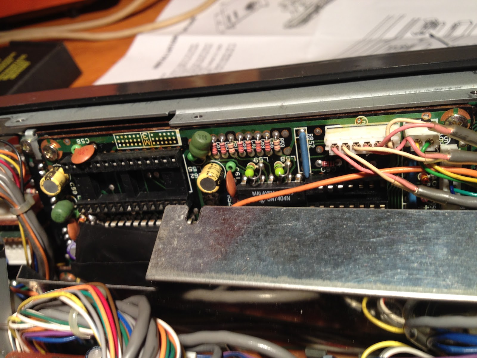
Finally, you will be able to see the two sockets for the two ICs.  The part of the IC with the half-circle indicates the location of pin one.  This view is from the top of the radio, and pin one goes to the left:

I forgot to take a picture before I put the heat shield back on, but this is what it looks like with the IC installed.  I had to compress the pins on the ICs a bit to get them installed, which is common.  Just be careful not to bend them too much, else they may break.

Put the radio back together in the reverse order of above, and you will be off to the races!

 This is the rig control interface for HRD, you can see where I have set the frequency to the 20m PSK calling frequency:

And this is the radio after reassembly and being controlled by the PC.  The downside to this is that you cannot control the volume, nor can you get current S-level readings from the radio back into the software like you can with newer rigs.  But being able to control a 20 year old radio via the PC at all is awesome!!


Put this project together with the soundcard interface that I build in an earlier post, and you have a fully functional rig for digital modes on the ham bands!  This was a really easy and fun project and I gained a lot of useful functionality from my rig!

73,

Richard, KK4JDO

Sunday, July 22, 2012

Rainy afternoon project with the kids: Coax Tester!

After finishing up the souncard interface yesterday, I thought that I would be done for a few days, but a house full of boisterous kids on a rainy day dictated otherwise.  As they say, necessity is the mother of invention, or in this case, maintaining my sanity was...  ;-)

I recalled watching a YouTube video by W5CYF (Tinker John) on how to make a simple go/go-go coax tester.  It seemed like a good project for the kids and I to do.  Like John, I used a green LED to mean the coax is bad, but hey, it's what I had on hand.

This is a simple, quick and dirty schematic of what we built:


In a project list this, there are a few things that kids can do, and a few that an adult needs to do.  While watching the kids play with the drill or soldering iron would be entertaining in a scary sort of way, the trip to the hospital afterwards would have been annoying.  However, seven year olds are good at sorting resistors by color, and 9 year olds are good at tightening screws.  They are also both helpful when small parts are dropped by fumble fingered parents.  Just remember that kids are kids, and tend to be distracted and not remember the goal.  They also like to fidget A LOT.  My son got to spend a few minutes in his room due to this, but he settled down and was back for the finish and testing.

My Parts List:

  • 1 x SO-239 connector
  • 1 x 9V battery connector
  • 1 x 350 Ohm resistor
  • 1 x Green LED
  • 1 x Small project box
  • 1 x 7 year old boy
  • 1 x 9 year old girl

Time to Completion:
  • About two hours, after all, the kids were helping me!  ;-)

Here are a few pics:

Here are the two proud builders!

Picture of the tester.

In this picture, I used a small bit of solder to simulate a piece of bad shorted coax.  Notice the green LED is on.  Green usually means good, but in this case, green is NO-GO!


Again, this was a fun little project that will give you an absolute basic go/no-go test of a piece of unknown coax.  It won't tell you impedance or length, if you need those tests go get an MFJ-259B or something similar.  If you want to make sure that you don't have a dead short and won't blow up your finals, this is the tool for you.  ;-)

73,

Richard, KK4JDO


Saturday, July 21, 2012

Soundcard Interface for APRS/Packet - Part 2

Well, I finally got the PTT part of the soundcard interface working.  This was fun, and sometimes frustrating, but very educational.  I am lacking in my understanding of component level electronics engineering.  As a network engineer, I would be comfortable designing and implementing an enterprise network for a new hospital (that's a different story), but understanding why a transistor works the way it does is beyond me at this point.  So I kind of fumbled my way through this.  One thing that is very important in network engineering is attention to detail, and solid planning.  For some reason I didn't carry this over to this project, and it bit me..lol

Let me state, for the record, plan your work, and work your plan.  Don't just wing it.

Okay, on that note, on to the project.  Once again, soundcardpacket.org was a great source of information on getting this part working.  I used this schematic from their site (click on the image to see more details):


R1 = Resistor, e.g. 1K2, to reduce voltage on the IC pin 1
IC =  Integrated Circuit; this sketch shows an IC, such as a 4N33
        or PS2603 Optocoupler, which uses a Darlington pair transistor.
        (Note: to identify pin #1, look for a small embossed circle on
         the top of the IC above pin 1; or looking into the notch in one
         side of the IC with the pins down, pin #1 is to the right of the notch.)
D1 = Diode, e.g. IN4001, would shunt any potential reverse voltage
        that might damage the sensitive diode/emitter in the IC.
        (Note: the band printed on the diode marks the cathode end,
        which attaches to the Serial Port/IC Pin 1 line in the sketch above.
        The opposite/anode end attaches to Ground.)


In the last post about this project, I built the receive and transmit cables that connect the output of the radio to the input on the soundcard, and the output on the soundcard to the input on the radio.  This worked well for listening to APRS and packet conversations, but I couldn't join in without manually keying the mic, which works okay if you're doing PSK31 or other HF digital modes, but isn't as easy with packet or APRS.  With this addition, a signal is sent via the PC's comm port to key the PTT circuit on the radio.  This allows the radio to be keyed via software instead of manually.  This allows things like APRS beacons to work normally.

This particular design uses an optocoupler to isolate the radio and the PC, while still allowing communications to flow.  This, along with the audio transformers used in the last post, helps to eliminate ground loops and voltage differentials, which are a source of hum in your transmission audio.

While building my version, I found that I didn't have the required 1.2K Ohm resistor, so I substituted a 1K and a 220 Ohm resistor in series.  This took a little additional space, which was at a premium in the tiny project box that I used, but ended up working well.  As you'll recall, in the last post, I decided to build this in a project box, instead of as a set of cables.  I think that in the long run my way will be more durable since there will be less movement of the internal solder joints due to cables wiggling around.  Time will tell.

A couple of issues that I ran into:

  1. On Windows XP (need to upgrade my shack PC), the serial mouse driver keeps the RTS pin HIGH, which causes the mic to key if nothing has taken ownership of the comm port that you are using (AGWPE, Digipan, etc) to bring it LOW.
  2. The pinout of the IC that I used was different than the one pictured in the schematic, don't blindly trust any schematic, do your homework first.  It saves solder (and frustration)
  3. Don't use too small of a project box, it is easier to do things if you have the room to do them in.

A couple of lessons that I learned:
  1. When if doubt, check solder joints.
  2. Follow the voltage, step through the circuit with a multimeter and make sure that you are seeing what you expect to see.
  3. Amperage kills...  This applies to ICs and other components as well as people.
  4. Be sure that the part is installed correctly BEFORE soldering...  

My Parts List:
  • 1 x 4N33 Optoisolator
  • 1 x 1K Ohm resistor
  • 1 x 220 Ohm resistor
  • 1 x IN4001 diode
  • 2 x 1/8" mono audio jacks
  • 1 x 6-pin mic connector to interface with my TR-7730
Time to Completion:
  • This part took me about eight hours due to lack of understanding and being too trigger happy with the soldering gun.  Next time should go smoother as hopefully I have learned my lesson on this.
Here are a couple of pics:

The IC and diode on the bottom right, and the two resistors on the bottom are all that make up this part of this circuit.  The other two resistors and the two transformers are for the rx and tx circuits.  You can also see the two audio jacks that I used to connect the PC and Radio.

This shows the completed and closed project box.  Again, while I at first thought that smaller would be better, after building it, I should have used a slightly larger box.  The next one that I build will be a bit bigger.

These are the cables that I built to connect the computer to the project box, and then on to the radio.  The gray DB9 connector attaches to the comm port for RTS based PTT.  The other end of that cable is an 1/8" mono connector that attaches to the project box.  The 6-pin cable actually has two pig-tales, one 1/8" mono for audio, and another 1/8" mono for the PTT signal.


And here is a shot of the APRS terminal showing me sending and receiving traffic.  I need a better antenna to hit more than one or two stations directly, but thankfully, one of the stations that I can hit is a digipeater/IGate.


All in all this project was a lot of fun and extremely educational.  It is also a LOT cheaper than buying another SignaLink.  I think that I have around $20 invested in this, plus my time.

73,

Richard, KK4JDO

Sunday, June 24, 2012

Update to the PTT Mic via USB Project

So since I've gotten into trying to learn Morse code, I needed some type of oscillator, so that I can hear my key as I practice.  You can purchase an oscillator from companies like MFJ, or you can make the on the cheap with a piezoelectric buzzer and a 9v battery.  I chose a slightly different route.

My option was to add a 1/4" jack to my PTT desk mic via USB project box.  I did keep the piezo buzzer in case I wanted to practice without interacting with the PC, but I am currently using a program called MorseRabbit, which can accept input from the keyboard spacebar.  Only, in this instance, the input is coming from my straight key, which in turn is connected to the Teensy USB microcontroller, which is emulating a keyboard.

My Parts List:

  • 1/4" mono audio jack (panel mount)
  • 5v piezo buzzer
  • bit of wire and solder
Time to Completion:
  • 30 minutes, including adding the necessary code to the "sketch"
Here is a pic:


Here is a copy of the code "sketch" that I am using:

#include <Bounce.h>

Bounce button0 = Bounce(0, 10);
Bounce button1 = Bounce(1, 10);

void setup() {
  pinMode(0, INPUT_PULLUP);
  pinMode(1, INPUT_PULLUP);
  pinMode(12, OUTPUT);
  pinMode(14, OUTPUT);
}

void loop() {
  // Update all the buttons.  There should not be any long
  // delays in loop(), so this runs repetitively at a rate
  // faster than the buttons could be pressed and released.
  button0.update();
  button1.update();

if (button0.fallingEdge()) {
   // press and release CTRL
   Keyboard.set_key1(KEYPAD_PLUS);
   Keyboard.send_now();
   Keyboard.set_key1(0);
   Keyboard.send_now();
   analogWrite(12, 200);
  }

 if (button0.risingEdge()) {
   // press and release CTRL
   Keyboard.set_key1(KEYPAD_PLUS);
   Keyboard.send_now();
   Keyboard.set_key1(0);
   Keyboard.send_now();
   analogWrite(12, 0);
  }
  
if (button1.fallingEdge()) {
   // press and hold space
   Keyboard.set_key1(KEY_SPACE);
   Keyboard.send_now();
   analogWrite(12, 200);
   //analogWrite(14, 255);
  }

 if (button1.risingEdge()) {
   // release space
   Keyboard.set_key1(KEY_SPACE);
   Keyboard.set_key1(0);
   Keyboard.send_now();
   analogWrite(12, 0);
   //analogWrite(14, 0);
  }  
}


You have to forgive the sloppy wiring, it was too much hassle for this project to etch a pc board.  Now I have the ability to practice CW on my PC, both sending and copying!

73,

Richard, KK4JDO


Sunday, June 17, 2012

Mic Adapter

I was recently in a position where I had a 2m radio that needed a new mic.  Specifically, I have a Yaesu FT-2200 that I picked up from eBay on the cheap.  This supposedly perfectly working radio had a myriad of issues, one of which being a mic with two bad capacitors.  One solution was to go purchase a new mic.  Well, this is an older radio, so they don't make mics specifically for this rig any longer.  However, I was able to find a suitable replacement, the only down side being that said replacement cost almost as much as I paid for the radio!  That wasn't gonna happen.  Another option was to rewire a mic that I already own to use with this radio.  The downside was that I actively use both mics, one for my Kenwood TS-440S, and the other (wired for the Kenwood), I use via my USB PTT box with EchoLink.  So I didn't really want to rewire either of those.

The final solution was a mic adapter!  It was a little aggravating to build as I had to cross between two vendors that do things slightly different (Kenwood uses two grounds, one for the mic, one for the PTT, while Yaesu uses a single common ground).  But it wasn't really all that bad, and seems to work.  Now I just need to get my Moxon mounted where I can use it, and I can talk on my preferred repeater without being all scratchy!

My Parts List:

  • 1 x 8-pin female mic connector
  • 1 x 8-pin male mic connector
  • 1 x 1' length of mic cable (initially I used Cat-5e, which worked good also)
  • 1 x 3" length of 1/2" PVC
  • 1 x 1/2" PVC cap


Time to Completion:

  • It took around 30 minutes to make, including scrounging the PVC to hold the male side of the connection since I didn't have a non-chassis mount connector handy.


Here is a pic:


This was an easy project that was a quick fix for a problem, and certainly cheaper than buying a new mic!

73,

Richard, KK4JDO

Tuesday, June 12, 2012

Intermod and Spurious Emissions!

So, as I was scanning the 10m band, I noticed that I was receiving occasional bursts of static on my 2m radio.  These were occurring as I crossed fairly strong carriers, which means that these carriers were interacting with my rig in receive mode, and causing what is called intermodulation, which was resulting in a spurious emission.

Here are some links for more reading on these phenomena: 


I recorded a quick video of it to show folks that just because you are using a receiver, it does NOT mean that you are not also broadcasting a signal!  Something to be mindful of, especially if you are in an area that is sensitive to RF fields (thinking of mining sites that use an RF signal to detonate explosives, among other scenarios).


I should probably point out that the volume on the radio that I am adjusting is completely down, the only radio that has its volume turned up is my Yaesu FT-2200 2m radio.  The sounds that you are hearing are the spurious emissions generated by my TS-440S tuned to ~28.5MHz being received by my FT-2200 on 147.120MHz.  I should also point out that these are extremely localized and can not be picked up beyond my shack.  I tried with an HT in the yard under the dipole and got nothing.  Also, I apologize for the poor quality of the video, I shot it with my iPhone 3GS, which has a pretty lousy camera.

73,

Richard, KK4JDO

Using a PTT desk mic on a PC

So in this post, I'm going to talk about a cool project that I finished a few weeks ago.  I like to use EchoLink (http://www.echolink.org/) to chat with people all over the world.  One of the uses for EchoLink, and the only thing that I use it for, is to connect to a repeater that you are too far away to hit using RF alone.  This software connects you to that repeater, and broadcasts what you say into your PC mic as if you were using a radio.  That being said, I like to feel like I am talking into a real rig, instead of talking on Skype or some other VoIP application when I am using EchoLink, especially since it is only accessible by other licensed Hams.  To that end, I had an old mic laying around, so I decided to connect it to the computer.  There were several obstacles that needed to be surmounted, the first being that the mic used an 8-pin connector for Kenwood HF radios, and the second being that you needed the press the PTT (Push-To-Talk) button in order for your audio to be sent out of the mic's audio pins.  The final issue was that the EchoLink software needs to be "keyed" as well by pushing down the space bar on your PC.  Here is how I solved these issues:

To convert from 8-pin to something that the PC could accept, I wired up the audio pins from an 8-pin male connector (the mic has a female, although it seems as though the names should be reversed) to an 1/8" female audio jack.  I mounted both in a small project box to make the assemblage a little easier to use.  This took care of getting the audio into the PC, but I still had to hit the space bar to "key" EchoLink, and at the same time hit the PTT button on the mic to connect the mic element to the audio pins inside the mic.  This was annoying to say the least.  Enter the Teensy USB Development Board:


This board connects to the PC and is recognized as one of several devices, a keyboard, a flash device, a MIDI device, etc.  The main one that I am concerned with was the ability to emulate a USB keyboard.  I soldered a connection from the PTT pins in the mic jack to one of the digital pins on the Teensy board, and another one to the ground pin.  This allows me to detect when the PTT button is depressed on the mic.  I then took this detection, and triggered a key press event to key EchoLink!  Now I can use EchoLink just like a normal radio, via the desk mic, without keyboard input.  Just for fun, I added a red LED to know when the mic PTT key is depressed (to hopefully avoid "hot-mic" issues).

My Parts List:

  • 1 x Teensy USB Board ( http://www.pjrc.com/teensy/)
  • 1 x Project Box
  • 1 x 8-pin male mic connector
  • 1 x 1/8" (3.5mm) audio connector
  • 1 x Red LED
  • 1 x 220-Ohm resistor


Time to Completion:

  • About four hours including figuring out the code for the "sketch" on the Teensy board.


Here is the simple schematic:


Here are a few pics:


Here is the code that I used on the Teensy board (which uses the Arduino IDE environment):


#include <Bounce.h>


Bounce button0 = Bounce(0, 10);


void setup() {
  pinMode(0, INPUT_PULLUP);
   pinMode(12, OUTPUT);
}


void loop() {
  // Update all the buttons.  There should not be any long
  // delays in loop(), so this runs repetitively at a rate
  // faster than the buttons could be pressed and released.
  button0.update();


if (button0.fallingEdge()) {
   // press and release CTRL
   Keyboard.set_key1(KEYPAD_PLUS);
   Keyboard.send_now();
   Keyboard.set_key1(0);
   Keyboard.send_now();
   analogWrite(12, 200);
  }


 if (button0.risingEdge()) {
   // press and release CTRL
   Keyboard.set_key1(KEYPAD_PLUS);
   Keyboard.send_now();
   Keyboard.set_key1(0);
   Keyboard.send_now();
   analogWrite(12, 0);
  }
}

Well, that's all for this post, I hope that you have enjoyed it, I certainly enjoyed making it!

73,

Richard, KK4JDO
Monday, June 11, 2012

The Obligatory Shack Pic

So now I can show you what all of those antenna are used with!  This is a quick overall shot of my "shack" as it stands right now.  I am considering some upgrade options in the near future, so stay tuned to see what kind of rig takes center stage (thinking TS-2000 for the shack and IC-7000 or FT-857D for the truck).


Included in this pic are:

Kenwood TS-440S, 20 years old and still talking around the world!  (just talked to Russia and Ukraine!)
Yaesu FT-2200 (look for an upcoming post on lessons learned about eBay)
MFJ-941D Antenna Tuner
Heath 3A power supply for testing purposes
Kenwood PS-30 for powering the TS-440S
SignaLink USB for APRS and other digital modes (trying to talk to the ISS, but need higher gain antenna)
Wouxun UV3D HT
Kenwood TS-120S (not feeling so well these days)
Homebrew PTT Mic to USB adapter to allow me to use my desk-mic with EchoLink (look for a future post)
Shure 256T desk mic
Kenwood MC-50 desk mic
El-cheapo CW straight-key (again, look for an upcoming post)
Radio Shack SWR/Power meter


Here are some more pics:


So that sums up my current shack.  More details as things change!

73,

Richard, KK4JDO

Last antenna post for now... ;-)

Okay, last one for now.  So the j-pole works pretty well, but I was still staticy when transmitting.  What I needed was a directional antenna for maximum gain.  Again, purchasing one at the Candy Store would have been $50 or more.  But for less than $8 at Home Depot, I was off and running.  When I use this antenna, I am full-quieting on the repeater.  The downside for me right now is that I cannot permanently mount this one outside, as I need to be in the front of the house to point at the repeater that I like to use (147.120MHz,+600,PL-103.5).

My Parts List:


  • 10' of 8AWG copper wire (enough for about three antenna like this, I want to make one for 70cm also)
  • 10' of 3/4 PVC pipe (again, enough for multiple antenna)
  • 50' of RG-58 coax


Time to Completion:


  • About four hours


Here is a pic:


More information on this type of antenna can be found at:

http://www.moxonantennaproject.com/

I have to say that I am impressed with how well this antenna functions!  The one thing that I do need to add is a balun at the feed-point, that is on the project list!  ;-)

73,

Richard, KK4JDO

And another antenna!

Alright, this is almost the last one for now, I promise.  I needed something to get better reception on my little handheld Wouxun HT, but didn't feel like spending $25 or so for one from the local ham store (referred to by other hams as the Candy Store).  My solution was to build a roll-up j-pole antenna out of left-over twinlead from my dipole.  Again, before I was not able to use my HT from home as the repeater is clear across town from where I live, and 5W wasn't going to cut it with the little rubber-duck that came with the HT.

My Parts List:


  • 6' of 300-Ohm twinlead
  • 10' of RG-58 coax with a PL-259
  • 1 PL-259 to Reverse-SMA adapter (had to buy this one, too much of a pain to make it)


Time to Completion:


  • 30 minutes or so


Here is a pic:


So admittedly I need a better pic of this one.  I'll work on that...

73,

Richard, KK4JDO

First Antenna, 1/2 wavelength 10m dipole

Hi All,

So, since this is about Ham Radio, you had to have guessed that there would be talk about various types of antenna.  I have a terrible dislike of spending money, so instead of buying my first antenna, I decided to build one instead.

As a newly minted Technician class Ham Radio Operator, the only HF bands that you have voice privileges on is the 10-meter band (28.3MHz - 28.5MHz).  You can operate CW on a few lower bands, but since I am still in the process of learning Morse Code  (CW), I decided to build an antenna for use where I can talk on voice (using what is called SSB or Single Side Band).

A dipole is a very basic antenna, and very easy to build.  Basically, you need some wire, and something to use as a feedline, such as coax or twinlead.

My Parts List:


  • 20' of stranded copper wire
  • 1 x 3/4" PVC "T" fitting
  • 2 x 2" pieces of 3/4" PVC pic as insulators
  • 20' of nylon rope
  • 100' of 300-Ohm twinlead from Radio Shack


Time to Completion:


  • One hour to measure, cut, solder, mess-up, re-do, and finish.
  • One additional hour to hang between two trees.


Here is a quick pic:


Once it was up in the air, I connected it to my radio via my tuner, and was talking to California, Idaho, Montana using SSB on 28.4MHz!

That it for this post, hope you enjoyed it!

73,

Richard, KK4JDO