Our thoughts and prayers go out to those affected by the terrible tornado in Oklahoma. I'm sure that ham radio operators and Skywarn members are doing their best to help out in the terrible situation there. If you would like to donate to help out, I found the following news article that lists several charities and support organizations:
http://usnews.nbcnews.com/_news/2013/05/20/18381508-how-to-help-oklahoma-tornado-victims?lite
I hate having to mention it, but beware of scams when donating. It seems that the scum of humanity comes out to prey on the good intentions of others during times like this, so carefully vet the charity that you are planning on donating to.
Not that anything could ever help if you are in the direct line of fire from an EF5 tornado, but being prepared for a disaster may give you that razor thin edge needed to survive.
If you are in a disaster prone area (I live in Central Florida, where we got four hurricanes in one year's time back in 2004), stock up on food, water, medical supplies, and anything else that you need on a daily basis. Consider joining Skywarn, ARES, or RACES as they supply training in how to prepare and how to cope and even be helpful to others in the event of an actual disaster. You can also go to FEMA's website and take free online training to learn how to integrate into SAR teams and work effectively with local firefighters and police if you are inclined to help others during an emergency.
This goes beyond the technical assistance that most hams think of in terms of assisting with emergency communications. While that is definitely needed, you also need to know how to dig through debris with other teams to find survivors in a coordinated manner so that you can be as quick and efficient as possible. Time is Life in this type of situation!
Again, my family and I will be praying hard for those impacted by this horrific storm. We are not directly involved in any way, but we are still devastated by the loss of life, particularly that of children. We cried our eyes out last night when we heard. Our sympathies go out to everyone involved!
Showing posts with label ham. Show all posts
Showing posts with label ham. Show all posts
Tuesday, May 21, 2013


Saturday, March 23, 2013
Wish List
I thought that I'd share a wish list today. I'm next expecting anyone to give me this stuff, just wanted to post the direction that I'm heading in the shack. And maybe give my XYL some hints for my birthday and Father's day... ;-)
It'll also be neat to look back over this list in a few years and see how my wants have changed and if I actually managed to acquire any of this.
For the shack:
It'll also be neat to look back over this list in a few years and see how my wants have changed and if I actually managed to acquire any of this.
For the shack:
- Palstar AT2K
- HF Amp
- Shure SM-7B Mic w/ boom
- 6m/2m/70cm verical
- 6m/2m/70cm triplexer
- Bencher Iambic Paddle
- Uniden HOME PATROL Scanner
- Telepost Inc LP-100A Power/SWR meter
- Telepost Inc LP-500 Station Monitor
For the truck:
- Kenwood TS-480SAT
- GPS with NMEA out
- Tarheel 100A-HP
- Uniden BCD-996XT Digital Scanner
- Icom ID-1 (look for an upcoming post on what I want to do with the truck)
- Icom IC-2820H with D-STAR and GPS module
For the bench:
- Tektronix 465 O-Scope
- Hakko Hot Air Rework Station
- Drill Press
- PCB Drill
- Capacitor tester
Of course, since I'm dreaming I might as well wish for a new QTH with dedicated room for my shack, and a 300' tower with stacked mono-band beams for all bands, a couple of beverage or rhombic arrays for receive and enough cash not to have to work ever again so that I can enjoy my hobby full time. ;-D
Anywho, thanks for reading my pointless post of the day! ;-)
73,
Richard, KK4JDO
Sunday, January 20, 2013
PSK - Papa Sierra Kilo
Or, according to some: Poland Sugar Kilowatt and to others: Platypus Simultaneous Kraken. Or maybe as it actually means, Phase Shift Keying. This appears to be a typical mid-day mid-winter propagation on 15 meters today. I'm guessing that I need to get on the air at a different time to get a different part of the world, but I am having a blast trying to work all of the countries in Europe!

I used to stick just to 20m for PSK, but one day I decided to branch out a bit. I have shied away from 10m since I upgraded to General class a few months back, but on a lark I decided to give it a shot on PSK. WOW! I worked 15 new DXCC entities in that one hour session. I am now hooked. So given the success of that endeavor I just jumped in with both feet on 15m. Once again, WOW! I had really been missing out on the action by staying on a single band. 60+ QSOs and 31 new DXCC entities later I use the following schedule (time and work permitting):

I used to stick just to 20m for PSK, but one day I decided to branch out a bit. I have shied away from 10m since I upgraded to General class a few months back, but on a lark I decided to give it a shot on PSK. WOW! I worked 15 new DXCC entities in that one hour session. I am now hooked. So given the success of that endeavor I just jumped in with both feet on 15m. Once again, WOW! I had really been missing out on the action by staying on a single band. 60+ QSOs and 31 new DXCC entities later I use the following schedule (time and work permitting):
- 10m (28.120.15) mid morning
- 15m (21.070.15) late morning
- 20m (14.070.15) mid day
- 40m ( 7.035.15) evening
There is some blurring of those time frames, but that is the gist of it. I don't have an antenna that works well on 80m, but I do listen there occasionally both phone and PSK, otherwise I would be working that band in the late evenings as well. Why don't you give PSK a try and come have a QSO with me on the bands!
73,
Richard, KK4JDO
Wednesday, November 7, 2012
Mobile mounts
I just got my new mounts in today for the radios that I built the console for in the last post! I've been trying to figure out how to mount the antennas for my radios in such a way that they work good and look good.
When I only had a single radio in the truck I used a Comet hood-lip mount with matching coax connector. This mount works okay, but it is a bit bulky. I have never been a fan of lip mounts as they sometimes deform the surface that they are attached to. This one seems to be large enough to spread the stress out over a fair area and may alleviate this issue. I haven't seen any deformation in the six months that I've had it on. Here is a pic of the truck with this mount using a 38" Diamond 2m/70cm half-wave antenna.


As I said, this mount seems to work pretty well. But I wanted to add a second or third antenna without starting to look like a four-poster bed. So I decided to investigate stake-pocket mounts to relocate this antenna and add the additional antenna for the CB in the other stake pocket. After much searching and reading I decided to order some mounts from Breedlove Mounts out of Gastonia, NC. They had amazing reviews and seemed like a good deal. I ordered the EZN Flat mount Model #14 (SO-239) and the Model #55 (3/8" stud) mounts.
I ordered these mounts Sunday evening off of their website, and the arrived with today's mail (Wednesday). Pretty quick service! The mounts appear to be extremely well made. The craftsmanship is top notch and you definitely get your money's worth. Here are a few pics, front and back, of the mounts that I ordered:


As you can see, these are extremely well made and rugged. The only thing that I would suggest is adding some anti-seize compound to the screws. This should keep the stainless steel screws from possibly spalling in the aluminum mount over time.
So once I moved the Diamond antenna from the front to the back and installed the Hustler FG-27S I was completely happy with the results. The mounts were strong and stable, as well as providing a good grounding solution that is drilled and tapped into the bottom of the bracket.


This turned into more of a review than a project, but I hope that you've found it informative. In an upcoming post I'll cover the coax runs and the DC grounding. I need to do some additional grounding for the radios, as well as under the truck to try to quite it down electrically.
73,
Richard, KK4JDO
When I only had a single radio in the truck I used a Comet hood-lip mount with matching coax connector. This mount works okay, but it is a bit bulky. I have never been a fan of lip mounts as they sometimes deform the surface that they are attached to. This one seems to be large enough to spread the stress out over a fair area and may alleviate this issue. I haven't seen any deformation in the six months that I've had it on. Here is a pic of the truck with this mount using a 38" Diamond 2m/70cm half-wave antenna.

As I said, this mount seems to work pretty well. But I wanted to add a second or third antenna without starting to look like a four-poster bed. So I decided to investigate stake-pocket mounts to relocate this antenna and add the additional antenna for the CB in the other stake pocket. After much searching and reading I decided to order some mounts from Breedlove Mounts out of Gastonia, NC. They had amazing reviews and seemed like a good deal. I ordered the EZN Flat mount Model #14 (SO-239) and the Model #55 (3/8" stud) mounts.
I ordered these mounts Sunday evening off of their website, and the arrived with today's mail (Wednesday). Pretty quick service! The mounts appear to be extremely well made. The craftsmanship is top notch and you definitely get your money's worth. Here are a few pics, front and back, of the mounts that I ordered:

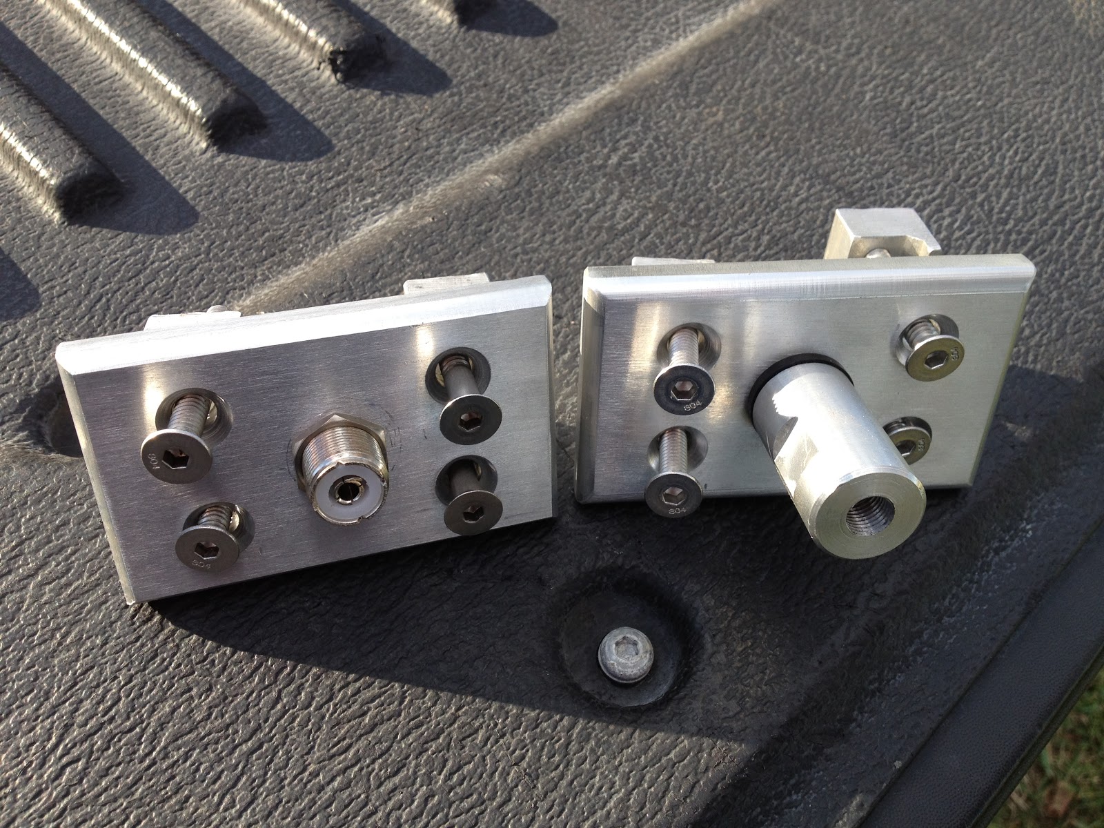
As you can see, these are extremely well made and rugged. The only thing that I would suggest is adding some anti-seize compound to the screws. This should keep the stainless steel screws from possibly spalling in the aluminum mount over time.
So once I moved the Diamond antenna from the front to the back and installed the Hustler FG-27S I was completely happy with the results. The mounts were strong and stable, as well as providing a good grounding solution that is drilled and tapped into the bottom of the bracket.


This turned into more of a review than a project, but I hope that you've found it informative. In an upcoming post I'll cover the coax runs and the DC grounding. I need to do some additional grounding for the radios, as well as under the truck to try to quite it down electrically.
73,
Richard, KK4JDO
Tuesday, November 6, 2012
Mobile Install
I drive a 2011 Ford F-150, which is not the most radio friendly of vehicles. It's not the worst, but it is not the best either. When I only had a single radio in the truck, it was fairly easy to accomplish a professional looking installation. As I added an 11m radio, and then a scanner, things got more difficult. I ended up deciding that I needed to build a console in place to house these additional radios.

The first radio that I put into the truck was a Yaesu FT-2900R, which is a 2m mono-band ham radio. This F-150 has a cubby hole at the bottom of the dash under the climate controls, which fit this radio like a glove while conveniently allowing plenty of air circulation to help cool this 75W solid aluminium beast. I took out the cubby hole section, removed the back of it with a dremel, mounted the radio inside, and *bam*, it looked like original equipment (of course, that was before this blog, so no pictures). The only downside was that it was a little difficult to see the top of the display on the FT-2900R to see if the offsets and tones were on at a glance. This worked fine and dandy for months...

Enter a Galaxy DX-959 CB radio (if you're a ham and hate on CB'ers, keep it to yourself, I like to be able to talk to the truckers while making long trips, and sometimes it's just fun). There is a world of difference between the way that a lot of CBs are built, versus the way that a lot of ham radios are built. First off, they tend to be bulkier and flashier. Needless to say, this wasn't going to fit in some handy preexisting pocket...


As you can see, the radios are held securely, but it definitely needed a top! This became in interesting problem. How to come up with something that would fit? Measuring would have been a major pain and I always mess that up anyway. So back to the cardboard! A snip here and a snip there, crumble it up, start over, and eventually, poof, a template is born! I then transferred that to some 1/4" plywood that I had laying around and got busy with the jigsaw. Eventually (and a few broken parts later) I had a top for the console!

But that's ugly, who wants to look at wood all day in a pickup? So how to finish it? I could paint it, but that would look funky. I could stain it, but again, wood... So I decided to cover it in vinyl. A local upholstery shop was nice enough to give me enough material to take care of it, after declining to do it for me (they were afraid of breaking it, which I understand since I broke a few). Again, the dilemma, how to actually do it? The final decision was to use the spray adhesive again, and just razor blade the holes for the radios. It actually turned out pretty well! The only downside was that the end-grain was exposed, but a handy sharpie marker took care of that...LOL!
The finished product turned out like this:


Please no comments about the state of the dirt on my floorboard. Consider it an experiment to see how long carpet survives without cleaning!
If I had it to do over again, I would try to cut the holes a little straighter with the jigsaw, and I would probably use some flat bar stock and build cradles for the radios to allow them to be serviced individually without massive effort and potentially marriage shattering language.
I'll attach a few more pictures, just because I can, and I am proud of this lash-up for some reason. ;-)


Yaesu FT-2900R
The first radio that I put into the truck was a Yaesu FT-2900R, which is a 2m mono-band ham radio. This F-150 has a cubby hole at the bottom of the dash under the climate controls, which fit this radio like a glove while conveniently allowing plenty of air circulation to help cool this 75W solid aluminium beast. I took out the cubby hole section, removed the back of it with a dremel, mounted the radio inside, and *bam*, it looked like original equipment (of course, that was before this blog, so no pictures). The only downside was that it was a little difficult to see the top of the display on the FT-2900R to see if the offsets and tones were on at a glance. This worked fine and dandy for months...
Galaxy DX-959
Enter a Galaxy DX-959 CB radio (if you're a ham and hate on CB'ers, keep it to yourself, I like to be able to talk to the truckers while making long trips, and sometimes it's just fun). There is a world of difference between the way that a lot of CBs are built, versus the way that a lot of ham radios are built. First off, they tend to be bulkier and flashier. Needless to say, this wasn't going to fit in some handy preexisting pocket...
Radio Shack PRO-2050
Then along comes a scanner that I had originally purchased for use inside, then got into the whole scanner thing and decided that I wanted more features available in the house. This makes for an interesting mounting challenge since there are no built-in mounting options on this scanner! This brings us back to the whole idea of building a console for this all to fit into.
I decided that if I built a console, it would need to house all three radios, not just the two additions. It would also need to look as stock as possible. And lastly, it needed to be cheap! I have seen some awesome custom professional installs but I have also seen some amazing price tags on them. Since I'm not on an episode of "Pimp My Ride", I had to have an affordable solution. I went through several iterations of the design, with the biggest issues being how to physically mount the radios in a small location. My final solution was to build a box that fit between the vertical trim pieces on the dash, and angle back to the seat. Originally, the radios were to be flush mounted, but to better make use of space I ended up angling the radios inside the new box. Additionally, the original though was to have the box be independent of radios so that I could remove them individually for service. However, space constraints dictated otherwise.
The end result was achieved by mocking up the sides of the box using cardboard to create a template, which was then cleaned up and copied to 11/32" plywood. Once this was done, I was able to start finalizing the placement of the radios that I had mocked up earlier on the cardboard. I ended up connecting the Galaxy radio directly to the plywood due to the space constraints mentioned earlier. So much for a modular design.
Since the scanner and the Galaxy radios were of similar size, they became the top and bottom spacers for the console. I then used some scrap 1"x 2" to secure the two pieces of plywood together front and rear. I used some scrap plywood to build a set of rails to hold the scanner in place, since it doesn't have a mobile mounting option. The Yaesu presented a problem, since it was over two inches narrower than the other radios! I ended up building spacers out of the 1" x 2", and mounting the 2m radio to them.
I then bought two $5 black rugs from Wal-Mart that closely resembled the carpet in my truck, and used a combination of 3M spray adhesive and carpet tacks to cover the sides of this contraction that I was putting together.
Once all this was done, I had to take the whole thing apart to install it into the truck. That turned out to be a pain in the rear! Things that line up easily on the bench sometimes don't work so well in real life. Such was the case with this console. No tweaking was needed, but maneuvering around in the confines of the pick-up when I'm decidedly in the fat-boy club was a challenge indeed! After much cussing and ill-will, things finally lined up properly and I was able to see my handy work:


But that's ugly, who wants to look at wood all day in a pickup? So how to finish it? I could paint it, but that would look funky. I could stain it, but again, wood... So I decided to cover it in vinyl. A local upholstery shop was nice enough to give me enough material to take care of it, after declining to do it for me (they were afraid of breaking it, which I understand since I broke a few). Again, the dilemma, how to actually do it? The final decision was to use the spray adhesive again, and just razor blade the holes for the radios. It actually turned out pretty well! The only downside was that the end-grain was exposed, but a handy sharpie marker took care of that...LOL!
The finished product turned out like this:


Please no comments about the state of the dirt on my floorboard. Consider it an experiment to see how long carpet survives without cleaning!
If I had it to do over again, I would try to cut the holes a little straighter with the jigsaw, and I would probably use some flat bar stock and build cradles for the radios to allow them to be serviced individually without massive effort and potentially marriage shattering language.
I'll attach a few more pictures, just because I can, and I am proud of this lash-up for some reason. ;-)


Eventually, I intend to add an Icom IC-7000 to the mix. I'm not sure whether I'll replace the Yaesu with it, or if I'll keep it so that I can monitor 2m or run APRS from the truck. What do you think I should do? Anyhow, if you've made it this far, you should be ready for bed, your insomnia has been cured!
73,
Richard, KK4JDO
Saturday, November 3, 2012
Quarter Wave Ground-Plane Scanner Antenna (and 2m ham antenna)
One of the purchases that I got via eBay is a Radio Shack PRO-2050 police/fire/etc scanner. I've never had a scanner before, and this was a cheap way to check it out. I didn't get a pick of it before I ended up moving it from the shack to the truck, so I nabbed a picture of the internet. Here is what my scanner looks like for those that haven't seen one:

Of course, since I had a scanner, I needed an antenna. I'm just getting into the whole scanner thing, so I didn't want to spend too much on the antenna since I didn't pay much for the scanner (which is several years old). One of the cheapest and easiest antennas to build is the quarter-wave ground plane. I had some #8 ground wire laying around, as well as an SO-239 connector, so I was off to the races.
There are several good calculators out there to help get the proper dimensions, however, the math is fairly simple:
468 divided by Frequency in MHz gives you the half-wave element length in feet.
The quotient from above divided by 2 gives you the quarter-wave element length in feet.
Take the quotient from the last problem and multiply it by 12, the product is the length of element in inches.
For example, if you want an antenna for the middle of the 2m ham band:
(468/146) / 2 x 12 = 19.23" which roughly equals 19 1/4" (since tape measures are in fractions of an inch).
It helps if you cut it a little long to allow you to tune to your specific location. I actually cut mine for resonance on the public services band (~150MHz) since that is what is in use in my area, however, I get acceptable performance on the 2m band as well (about 1.7:1 VSWR).
Bending the ground plane elements down to 45 degrees brings the resistance of the antenna closer to 50 Ohms. I'm not sure how this works exactly, maybe someone could drop a post and let me know why this works.
Here is a quick pic of the completed antenna. The ground plane elements sag a bit with they are supporting the weight of the antenna. They are straight when the antenna is suspended properly.

I also added vertical stubs for the 440MHz band as well as the 800MHz bands. I didn't add ground plane elements for them as I'm not sure that I would see any benefit from doing so since I have the 2m elements. Here is a close up of the verticals.

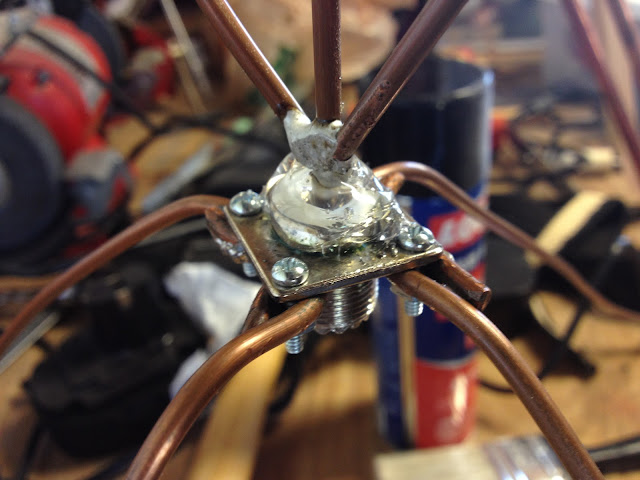
And the final thing that I need to do, as you can tell from the background of the picture above, is clean my work bench! It is getting crazy in there, so hopefully I can get that squared away soon.
My Parts List:

Of course, since I had a scanner, I needed an antenna. I'm just getting into the whole scanner thing, so I didn't want to spend too much on the antenna since I didn't pay much for the scanner (which is several years old). One of the cheapest and easiest antennas to build is the quarter-wave ground plane. I had some #8 ground wire laying around, as well as an SO-239 connector, so I was off to the races.
There are several good calculators out there to help get the proper dimensions, however, the math is fairly simple:
468 divided by Frequency in MHz gives you the half-wave element length in feet.
The quotient from above divided by 2 gives you the quarter-wave element length in feet.
Take the quotient from the last problem and multiply it by 12, the product is the length of element in inches.
For example, if you want an antenna for the middle of the 2m ham band:
(468/146) / 2 x 12 = 19.23" which roughly equals 19 1/4" (since tape measures are in fractions of an inch).
It helps if you cut it a little long to allow you to tune to your specific location. I actually cut mine for resonance on the public services band (~150MHz) since that is what is in use in my area, however, I get acceptable performance on the 2m band as well (about 1.7:1 VSWR).
Bending the ground plane elements down to 45 degrees brings the resistance of the antenna closer to 50 Ohms. I'm not sure how this works exactly, maybe someone could drop a post and let me know why this works.
Here is a quick pic of the completed antenna. The ground plane elements sag a bit with they are supporting the weight of the antenna. They are straight when the antenna is suspended properly.

I also added vertical stubs for the 440MHz band as well as the 800MHz bands. I didn't add ground plane elements for them as I'm not sure that I would see any benefit from doing so since I have the 2m elements. Here is a close up of the verticals.

The last thing that I did was to seal the top of the connector with some silicone caulking. This will help to keep water out of the coax, which would degrade the metal over time. I would have used coax-seal, but I ran out and didn't feel like spending the money on this antenna.

And the final thing that I need to do, as you can tell from the background of the picture above, is clean my work bench! It is getting crazy in there, so hopefully I can get that squared away soon.
My Parts List:
- 1 x SO-239 connector
- 8' of #8 grounding wire
- 4 x little screws
- Caulking
Time to Completion:
- About one hour for this one, mainly getting the jig built to solder the pieces together.
Next time I'll work on getting better pictures. I tend to feel my way through some of these projects and don't think to document as I fumble along.
73,
Richard, KK4JDO
And... We're back...
To anyone that cares, sorry that I haven't posted in such a long time. My real job as a systems engineer at a children's hospital can get hectic at times. On the bright side, we successfully opened a brand new, absolutely state of the art hospital in Orlando, FL. Check it out at >here<
In addition to working some completely insane hours, I also moved from the massively over-sized house in the burbs to a marginally under-sized house in the country. I'm into RC planes as well as Amateur Radio, so having a place with a lot more land allows me to enjoy both of my hobbies at home. It also helps that this place is cheaper to heat and cool being that it is around 1,200 sq ft smaller that the last house. Hopefully we'll be able to buy again in a few years.
I have had time for a few projects, mostly in the last week to two, and I have had some searches running on eBay and a few other sites (like QRZ.com). As a result of these searches I have been able to acquire a Kenwood TR-9500 that I really wanted, as well as the matching BO-9A base and matching PS-20 power supply. All that is left to have a complete system is the SP-120 speaker. These occasionally show up on various sites, so I'll keep my eye peeled for it. Here is a neat quick pic of my new rig:

The TR-9000 is on the middle shelf, left side (red freq display), and the TR-9500 is on the right side of the same shelf (green freq display).
Both of these rigs are all mode radios, so I have the ability to use single side band (SSB) in addition to CW and both narrow and wide band FM. This is handy as some of the older satellites use SSB. It also allows me to start dabbling in the world of VHF/UHF weak signal work, which takes place on SSB as well. It is kind of neat to see how far you can talk on what are usually local area bands. I am waiting on a Mirage B-108 to show up, which is an 80W amplifier that also contains a receive pre-amp to help with working low strength contacts. One of these days I want to check out EME, or "moon-bounce", but that requires some seriously high-gain antenna arrays or even dishes (like re-tasked old satellite TV dishs, the big Ka band ones, not the little 18" DirecTV trashcan lids).
I also built a couple of quick desks since I no longer have an office. I had to turn my "ham-shack" into a "ham-corner". I built two identical desks out of 3/4" plywood and 1x12 whiteboard. The main goal was to use as much vertical space as possible to maximize my storage options. They are not quite finished yet, I still need to add trim, and build the linking section to make is a complete corner desk instead of two stand-alone desks. Be at least I have a place to put my radios. Here is a quick pic of the desk with my ham gear on it. The other desk contains the gear that I use for work and is just to the left of it. Not that anyone really cares how my shack is set up...lol...but I thought that someone might be interested in how my desk is designed. Post a comment if you would like to see actual plans for them. ;-)

In addition to working some completely insane hours, I also moved from the massively over-sized house in the burbs to a marginally under-sized house in the country. I'm into RC planes as well as Amateur Radio, so having a place with a lot more land allows me to enjoy both of my hobbies at home. It also helps that this place is cheaper to heat and cool being that it is around 1,200 sq ft smaller that the last house. Hopefully we'll be able to buy again in a few years.
I have had time for a few projects, mostly in the last week to two, and I have had some searches running on eBay and a few other sites (like QRZ.com). As a result of these searches I have been able to acquire a Kenwood TR-9500 that I really wanted, as well as the matching BO-9A base and matching PS-20 power supply. All that is left to have a complete system is the SP-120 speaker. These occasionally show up on various sites, so I'll keep my eye peeled for it. Here is a neat quick pic of my new rig:

The TR-9000 is on the middle shelf, left side (red freq display), and the TR-9500 is on the right side of the same shelf (green freq display).
Both of these rigs are all mode radios, so I have the ability to use single side band (SSB) in addition to CW and both narrow and wide band FM. This is handy as some of the older satellites use SSB. It also allows me to start dabbling in the world of VHF/UHF weak signal work, which takes place on SSB as well. It is kind of neat to see how far you can talk on what are usually local area bands. I am waiting on a Mirage B-108 to show up, which is an 80W amplifier that also contains a receive pre-amp to help with working low strength contacts. One of these days I want to check out EME, or "moon-bounce", but that requires some seriously high-gain antenna arrays or even dishes (like re-tasked old satellite TV dishs, the big Ka band ones, not the little 18" DirecTV trashcan lids).
I also built a couple of quick desks since I no longer have an office. I had to turn my "ham-shack" into a "ham-corner". I built two identical desks out of 3/4" plywood and 1x12 whiteboard. The main goal was to use as much vertical space as possible to maximize my storage options. They are not quite finished yet, I still need to add trim, and build the linking section to make is a complete corner desk instead of two stand-alone desks. Be at least I have a place to put my radios. Here is a quick pic of the desk with my ham gear on it. The other desk contains the gear that I use for work and is just to the left of it. Not that anyone really cares how my shack is set up...lol...but I thought that someone might be interested in how my desk is designed. Post a comment if you would like to see actual plans for them. ;-)

One of the things that I am considering adding to the desks are a set of doors to hide the equipment when not in use. I'm using the corner of my bedroom, and while I'm okay with seeing my stuff all the time, my XYL is only marginally impressed with the whole ham radio out in the open concept. ;-)
Anyhow, I have a few other projects that I've been working on, and will work on adding those in additional posts this evening and in my "spare" time. For now, have a good evening!
73,
Richard, KK4JDO
Sunday, August 12, 2012
Wanted: Kenwood TR-9500
As you may have surmised from an earlier post where I added an SS-64 CTCSS encoder to a 2m radio, I already own a Kenwood TR-9000. In fact, I have the complete station which includes the radio itself, as well as the matching SP-120 speaker, PS-20 power supply, and BO-9 base "shelf". Here is a stock picture of this setup:

This is an absolutely awesome all-mode 2m VHF radio. It can do Wide-Band FM, Narrow-Band, USB, LSB, and CW. With the addition of the SS-64, it can also generate CTCSS tones to access repeaters. The radio that I'm looking for is almost identical to this one, except it has a green display and uses UHF (70cm) frequencies. Here is a closeup that I found online of that radio:


73,
Richard, KK4JDO

This is an absolutely awesome all-mode 2m VHF radio. It can do Wide-Band FM, Narrow-Band, USB, LSB, and CW. With the addition of the SS-64, it can also generate CTCSS tones to access repeaters. The radio that I'm looking for is almost identical to this one, except it has a green display and uses UHF (70cm) frequencies. Here is a closeup that I found online of that radio:

Ideally, I would like to get the same complete station as above. I think that it would be awesome to have a matched set of these radios.
The reason that I'm trying to acquire the aforementioned UHF radio is that I want to get into working other stations via Amateur Radio satellites. Operating via this mode requires you to transmit on one frequency (called the uplink frequency) and receive on a different frequency (call downlink). So you can see why I either need two radios, or one radio that is dual-band. I could go the dual-band route, but I have to be honest, I have fallen in love with this awesome little TR-9000 and would love to use it for this purpose as well as 2m DX and chit-chatting on local repeaters.
There are several ham radio satellites in orbit, which always serves to amaze non-hams, as well as a ham radio installation on the International Space Station. The station on the ISS sometimes acts like the other satellites, allowing you to talk to other Earth-based operators, and sometime operates as a normal ham station, allowing you to talk to the astronauts on the station itself. How cool is that?!
Here is a diagram of one of the amateur radio satellites currently in orbit. It is called Delfi-C3 (DO-64). It was launched a few years ago by the Delft University of Technology in the Netherlands as a student research project:

So, if you have one of these radios that you would like to part with at an even close to reasonable price, please let me know and maybe we can work something out!
73,
Richard, KK4JDO
Friday, August 10, 2012
Installing an IC-10 kit into a Kenwood TS-440S/AT HF Radio
I use Ham Radio Deluxe, or more specifically, Digital Master 780, for most of the digital mode communications that I do (usually just PSK31). This software is great and does a lot of awesome stuff. One of those cool things that you can do with HRD is rig control. This makes it easy to jump from frequency to frequency (QSY in ham-speak) from within the software, instead of having to tune the radio and adjust the software accordingly. It also keep your PC up-to-date on what frequency your radio is on for automated logging (really help for lazy guys like me).
Anyway, since I have an older radio, I had to modify it with an add-on kit, originally called the Kenwood IC-10 kit. Kenwood no longer sell this kit since they made the TS-440 over 20 years ago. However, since this kit is just basically two ICs (an 8251A and a TC4040BP), they can still be obtained. I got mine off of eBay for $20. This will allow 4800 baud serial communications via the ACC-1 interface on the back of the radio.
You can then use a round 6-pin DIN connector and a DB9 connector to make a serial interface cable. Be careful as the TS-440 ACC-1 interface uses TTL voltages (5V) and serial wants to use 12V, you will either need to use Kenwood's IF-232 kit to match the voltages, or use a USB-to-serial converter with normally operates at TTL voltage levels (beware Prolific chipsets).
The install process is fairly simple, it took me around 20 minutes to complete the installation, including the time it took to take the pictures.
This is a picture of the kit itself, basically a serial UART and a CMOS timer chip. Be sure to take static precautions, it would be a shame to do this install and have it not work due to fried ICs. Basically, just stay at the same electrical potential as the radio and you'll be fine. Never touch the chip without touching the radio first. You could also use a static strap, although I generally find this to be overly cautious unless you are working with extremely sensitive parts (or extremely expensive ones).

Below is a picture of the radio that we are about to perform surgery one, to wit, a Kenwood TS-440S/AT:

Step one is to remove the top cover, which consists of eight screws (four on top, two on each side):

Be sure when you remove the top that you keep track of where the speaker cable goes so that you can put it back together when you are finished. It is the yellow cable in this picture:

Next, flip it over and repeat the process with the bottom cover (nine screws this time, five on bottom, two on each side):

After that, remove the three screws on the bottom of the heat shield (silver part to the right with the three holes). Also remove the four screws (two on each side) that hold the front panel in place:

Then remove the two screws that hold the top of the heat shield on:

Finally, you will be able to see the two sockets for the two ICs. The part of the IC with the half-circle indicates the location of pin one. This view is from the top of the radio, and pin one goes to the left:
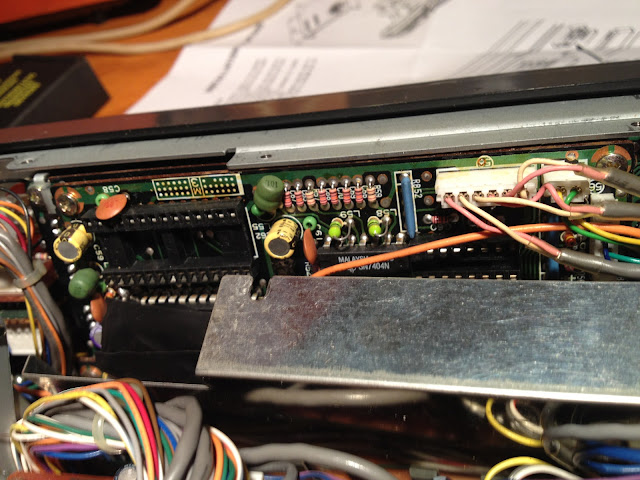
I forgot to take a picture before I put the heat shield back on, but this is what it looks like with the IC installed. I had to compress the pins on the ICs a bit to get them installed, which is common. Just be careful not to bend them too much, else they may break.
Put the radio back together in the reverse order of above, and you will be off to the races!

This is the rig control interface for HRD, you can see where I have set the frequency to the 20m PSK calling frequency:
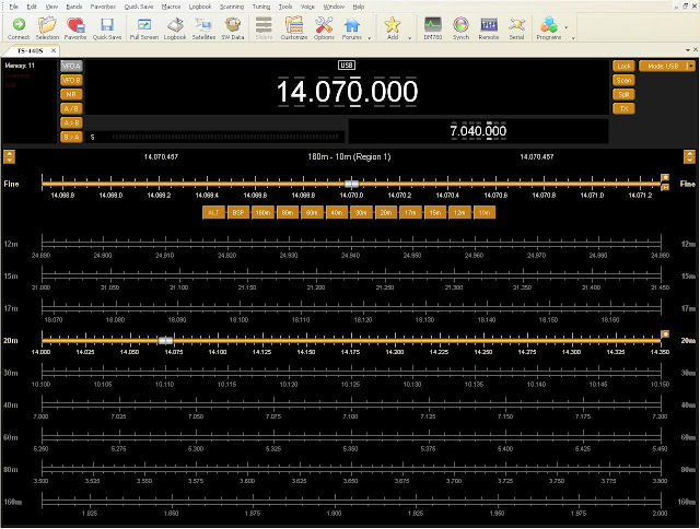
And this is the radio after reassembly and being controlled by the PC. The downside to this is that you cannot control the volume, nor can you get current S-level readings from the radio back into the software like you can with newer rigs. But being able to control a 20 year old radio via the PC at all is awesome!!

Put this project together with the soundcard interface that I build in an earlier post, and you have a fully functional rig for digital modes on the ham bands! This was a really easy and fun project and I gained a lot of useful functionality from my rig!
73,
Richard, KK4JDO
Anyway, since I have an older radio, I had to modify it with an add-on kit, originally called the Kenwood IC-10 kit. Kenwood no longer sell this kit since they made the TS-440 over 20 years ago. However, since this kit is just basically two ICs (an 8251A and a TC4040BP), they can still be obtained. I got mine off of eBay for $20. This will allow 4800 baud serial communications via the ACC-1 interface on the back of the radio.
You can then use a round 6-pin DIN connector and a DB9 connector to make a serial interface cable. Be careful as the TS-440 ACC-1 interface uses TTL voltages (5V) and serial wants to use 12V, you will either need to use Kenwood's IF-232 kit to match the voltages, or use a USB-to-serial converter with normally operates at TTL voltage levels (beware Prolific chipsets).
The install process is fairly simple, it took me around 20 minutes to complete the installation, including the time it took to take the pictures.
This is a picture of the kit itself, basically a serial UART and a CMOS timer chip. Be sure to take static precautions, it would be a shame to do this install and have it not work due to fried ICs. Basically, just stay at the same electrical potential as the radio and you'll be fine. Never touch the chip without touching the radio first. You could also use a static strap, although I generally find this to be overly cautious unless you are working with extremely sensitive parts (or extremely expensive ones).

Below is a picture of the radio that we are about to perform surgery one, to wit, a Kenwood TS-440S/AT:

Step one is to remove the top cover, which consists of eight screws (four on top, two on each side):

Be sure when you remove the top that you keep track of where the speaker cable goes so that you can put it back together when you are finished. It is the yellow cable in this picture:

Next, flip it over and repeat the process with the bottom cover (nine screws this time, five on bottom, two on each side):

After that, remove the three screws on the bottom of the heat shield (silver part to the right with the three holes). Also remove the four screws (two on each side) that hold the front panel in place:

Then remove the two screws that hold the top of the heat shield on:

Finally, you will be able to see the two sockets for the two ICs. The part of the IC with the half-circle indicates the location of pin one. This view is from the top of the radio, and pin one goes to the left:
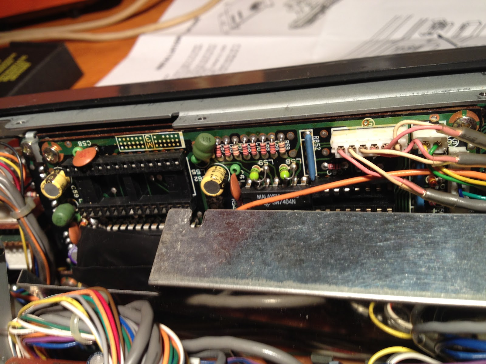
I forgot to take a picture before I put the heat shield back on, but this is what it looks like with the IC installed. I had to compress the pins on the ICs a bit to get them installed, which is common. Just be careful not to bend them too much, else they may break.
Put the radio back together in the reverse order of above, and you will be off to the races!


And this is the radio after reassembly and being controlled by the PC. The downside to this is that you cannot control the volume, nor can you get current S-level readings from the radio back into the software like you can with newer rigs. But being able to control a 20 year old radio via the PC at all is awesome!!

Put this project together with the soundcard interface that I build in an earlier post, and you have a fully functional rig for digital modes on the ham bands! This was a really easy and fun project and I gained a lot of useful functionality from my rig!
73,
Richard, KK4JDO
Signs of the times!
So I ordered this awesome LED lit sign for my ham shack! It cost $28 from ProjectGM. I liked it so much that I ordered several for my co-workers that have been laboring away with me trying to get our new hospital up and running!


You can get all different designs and all different colors of LED and wood bases. Give them a holler and tell them that I sent you! The business is run by a couple of hams in Ohio, my home state. I get nothing from advertising for them, but they have an awesome product at a great price.

Anyhow, I thought that this was pretty awesome, so I wanted to share!
73,
Richard, KK4JDO
Sunday, July 22, 2012
A Plethora of Project Boxes
As I was cleaning up after our little project this afternoon, it occurred to me that I am slowly accumulating a plethora of small project boxes. I find myself picking up another one every time I go to Radio Shack. In addition to the ones in the picture, I have two more in the parts bin...lol.
Anyhow, just thought that I'd share a picture of them. I've had a lot of fun so far with these projects, and I'm looking forward to many more! All that being said, here is a quick pic of my little project boxes:

Starting clockwise from the left, these boxes contain:
Anyhow, just thought that I'd share a picture of them. I've had a lot of fun so far with these projects, and I'm looking forward to many more! All that being said, here is a quick pic of my little project boxes:

Starting clockwise from the left, these boxes contain:
- Soundcard interface for APRS/Packet/and other digital modes
- PC interface for PTT desk mic and morse code straight key
- Control box for cycling through (manually, or enabling automatic shifting of) colors on my LED lit glass blocks.
- Simple Coax Tester
It pains me that I paid around $100 for the SignaLink and associated cables when I could have built an interface for around $20. Not knocking the SignaLink USB, it is a great device, but I like building things myself when possible.
73,
Richard, KK4JDO
Rainy afternoon project with the kids: Coax Tester!
After finishing up the souncard interface yesterday, I thought that I would be done for a few days, but a house full of boisterous kids on a rainy day dictated otherwise. As they say, necessity is the mother of invention, or in this case, maintaining my sanity was... ;-)
I recalled watching a YouTube video by W5CYF (Tinker John) on how to make a simple go/go-go coax tester. It seemed like a good project for the kids and I to do. Like John, I used a green LED to mean the coax is bad, but hey, it's what I had on hand.
This is a simple, quick and dirty schematic of what we built:

In a project list this, there are a few things that kids can do, and a few that an adult needs to do. While watching the kids play with the drill or soldering iron would be entertaining in a scary sort of way, the trip to the hospital afterwards would have been annoying. However, seven year olds are good at sorting resistors by color, and 9 year olds are good at tightening screws. They are also both helpful when small parts are dropped by fumble fingered parents. Just remember that kids are kids, and tend to be distracted and not remember the goal. They also like to fidget A LOT. My son got to spend a few minutes in his room due to this, but he settled down and was back for the finish and testing.
My Parts List:


I recalled watching a YouTube video by W5CYF (Tinker John) on how to make a simple go/go-go coax tester. It seemed like a good project for the kids and I to do. Like John, I used a green LED to mean the coax is bad, but hey, it's what I had on hand.
This is a simple, quick and dirty schematic of what we built:
In a project list this, there are a few things that kids can do, and a few that an adult needs to do. While watching the kids play with the drill or soldering iron would be entertaining in a scary sort of way, the trip to the hospital afterwards would have been annoying. However, seven year olds are good at sorting resistors by color, and 9 year olds are good at tightening screws. They are also both helpful when small parts are dropped by fumble fingered parents. Just remember that kids are kids, and tend to be distracted and not remember the goal. They also like to fidget A LOT. My son got to spend a few minutes in his room due to this, but he settled down and was back for the finish and testing.
My Parts List:
- 1 x SO-239 connector
- 1 x 9V battery connector
- 1 x 350 Ohm resistor
- 1 x Green LED
- 1 x Small project box
- 1 x 7 year old boy
- 1 x 9 year old girl
Time to Completion:
- About two hours, after all, the kids were helping me! ;-)
Here are a few pics:

Here are the two proud builders!

Picture of the tester.

In this picture, I used a small bit of solder to simulate a piece of bad shorted coax. Notice the green LED is on. Green usually means good, but in this case, green is NO-GO!
Again, this was a fun little project that will give you an absolute basic go/no-go test of a piece of unknown coax. It won't tell you impedance or length, if you need those tests go get an MFJ-259B or something similar. If you want to make sure that you don't have a dead short and won't blow up your finals, this is the tool for you. ;-)
73,
Richard, KK4JDO
Saturday, July 21, 2012
Soundcard Interface for APRS/Packet - Part 2
Well, I finally got the PTT part of the soundcard interface working. This was fun, and sometimes frustrating, but very educational. I am lacking in my understanding of component level electronics engineering. As a network engineer, I would be comfortable designing and implementing an enterprise network for a new hospital (that's a different story), but understanding why a transistor works the way it does is beyond me at this point. So I kind of fumbled my way through this. One thing that is very important in network engineering is attention to detail, and solid planning. For some reason I didn't carry this over to this project, and it bit me..lol
Let me state, for the record, plan your work, and work your plan. Don't just wing it.
Okay, on that note, on to the project. Once again, soundcardpacket.org was a great source of information on getting this part working. I used this schematic from their site (click on the image to see more details):

In the last post about this project, I built the receive and transmit cables that connect the output of the radio to the input on the soundcard, and the output on the soundcard to the input on the radio. This worked well for listening to APRS and packet conversations, but I couldn't join in without manually keying the mic, which works okay if you're doing PSK31 or other HF digital modes, but isn't as easy with packet or APRS. With this addition, a signal is sent via the PC's comm port to key the PTT circuit on the radio. This allows the radio to be keyed via software instead of manually. This allows things like APRS beacons to work normally.
This particular design uses an optocoupler to isolate the radio and the PC, while still allowing communications to flow. This, along with the audio transformers used in the last post, helps to eliminate ground loops and voltage differentials, which are a source of hum in your transmission audio.
While building my version, I found that I didn't have the required 1.2K Ohm resistor, so I substituted a 1K and a 220 Ohm resistor in series. This took a little additional space, which was at a premium in the tiny project box that I used, but ended up working well. As you'll recall, in the last post, I decided to build this in a project box, instead of as a set of cables. I think that in the long run my way will be more durable since there will be less movement of the internal solder joints due to cables wiggling around. Time will tell.
A couple of issues that I ran into:


Let me state, for the record, plan your work, and work your plan. Don't just wing it.
Okay, on that note, on to the project. Once again, soundcardpacket.org was a great source of information on getting this part working. I used this schematic from their site (click on the image to see more details):
R1 = Resistor, e.g. 1K2, to reduce voltage on the IC pin 1
IC = Integrated Circuit; this sketch shows an IC, such as a 4N33
or PS2603 Optocoupler, which uses a Darlington pair transistor.
(Note: to identify pin #1, look for a small embossed circle on
the top of the IC above pin 1; or looking into the notch in one
side of the IC with the pins down, pin #1 is to the right of the notch.)
D1 = Diode, e.g. IN4001, would shunt any potential reverse voltage
that might damage the sensitive diode/emitter in the IC.
(Note: the band printed on the diode marks the cathode end,
which attaches to the Serial Port/IC Pin 1 line in the sketch above.
The opposite/anode end attaches to Ground.)
In the last post about this project, I built the receive and transmit cables that connect the output of the radio to the input on the soundcard, and the output on the soundcard to the input on the radio. This worked well for listening to APRS and packet conversations, but I couldn't join in without manually keying the mic, which works okay if you're doing PSK31 or other HF digital modes, but isn't as easy with packet or APRS. With this addition, a signal is sent via the PC's comm port to key the PTT circuit on the radio. This allows the radio to be keyed via software instead of manually. This allows things like APRS beacons to work normally.
This particular design uses an optocoupler to isolate the radio and the PC, while still allowing communications to flow. This, along with the audio transformers used in the last post, helps to eliminate ground loops and voltage differentials, which are a source of hum in your transmission audio.
While building my version, I found that I didn't have the required 1.2K Ohm resistor, so I substituted a 1K and a 220 Ohm resistor in series. This took a little additional space, which was at a premium in the tiny project box that I used, but ended up working well. As you'll recall, in the last post, I decided to build this in a project box, instead of as a set of cables. I think that in the long run my way will be more durable since there will be less movement of the internal solder joints due to cables wiggling around. Time will tell.
A couple of issues that I ran into:
- On Windows XP (need to upgrade my shack PC), the serial mouse driver keeps the RTS pin HIGH, which causes the mic to key if nothing has taken ownership of the comm port that you are using (AGWPE, Digipan, etc) to bring it LOW.
- The pinout of the IC that I used was different than the one pictured in the schematic, don't blindly trust any schematic, do your homework first. It saves solder (and frustration)
- Don't use too small of a project box, it is easier to do things if you have the room to do them in.
A couple of lessons that I learned:
- When if doubt, check solder joints.
- Follow the voltage, step through the circuit with a multimeter and make sure that you are seeing what you expect to see.
- Amperage kills... This applies to ICs and other components as well as people.
- Be sure that the part is installed correctly BEFORE soldering...
My Parts List:
- 1 x 4N33 Optoisolator
- 1 x 1K Ohm resistor
- 1 x 220 Ohm resistor
- 1 x IN4001 diode
- 2 x 1/8" mono audio jacks
- 1 x 6-pin mic connector to interface with my TR-7730
Time to Completion:
- This part took me about eight hours due to lack of understanding and being too trigger happy with the soldering gun. Next time should go smoother as hopefully I have learned my lesson on this.
Here are a couple of pics:

The IC and diode on the bottom right, and the two resistors on the bottom are all that make up this part of this circuit. The other two resistors and the two transformers are for the rx and tx circuits. You can also see the two audio jacks that I used to connect the PC and Radio.

This shows the completed and closed project box. Again, while I at first thought that smaller would be better, after building it, I should have used a slightly larger box. The next one that I build will be a bit bigger.

These are the cables that I built to connect the computer to the project box, and then on to the radio. The gray DB9 connector attaches to the comm port for RTS based PTT. The other end of that cable is an 1/8" mono connector that attaches to the project box. The 6-pin cable actually has two pig-tales, one 1/8" mono for audio, and another 1/8" mono for the PTT signal.

And here is a shot of the APRS terminal showing me sending and receiving traffic. I need a better antenna to hit more than one or two stations directly, but thankfully, one of the stations that I can hit is a digipeater/IGate.
All in all this project was a lot of fun and extremely educational. It is also a LOT cheaper than buying another SignaLink. I think that I have around $20 invested in this, plus my time.
73,
Richard, KK4JDO
Subscribe to:
Posts (Atom)