Showing posts with label learning. Show all posts

Wednesday, December 26, 2012

OT: Christmas project with the kids

I managed to heat up the soldering iron and melt some solder during the weekend before Christmas, but it wasn't in pursuit of anything ham radio related.  I have a RockMite kit that I've been meaning to get to, but never seem to get around to it.  But no, this weekend's project was done with and for the kids.

While bumming around Radio Shack a few weeks ago I stumbled across the neatest little Velleman 3D Christmas tree kit!  It didn't look to complicated and was only $7 so I decided to give it a shot with the kids.  Now keep in mind, my kids (the two that were most interested in helping) are 7 and 10 so I couldn't do anything too complex, but this looked right up their alley!


Just like the last little project that I did with the kids, they are still too young to solder, but they can sort parts by type, sort resistors by color code and now they are old enough to actually put the components onto the board as well!  This kit comes with two boards that makes of the planform shape of a Christmas tree.  This worked out perfectly as each kiddo was able to get one board to work on.

The project did not require much in the way of tools.  A soldering iron, some solder, and some snips.
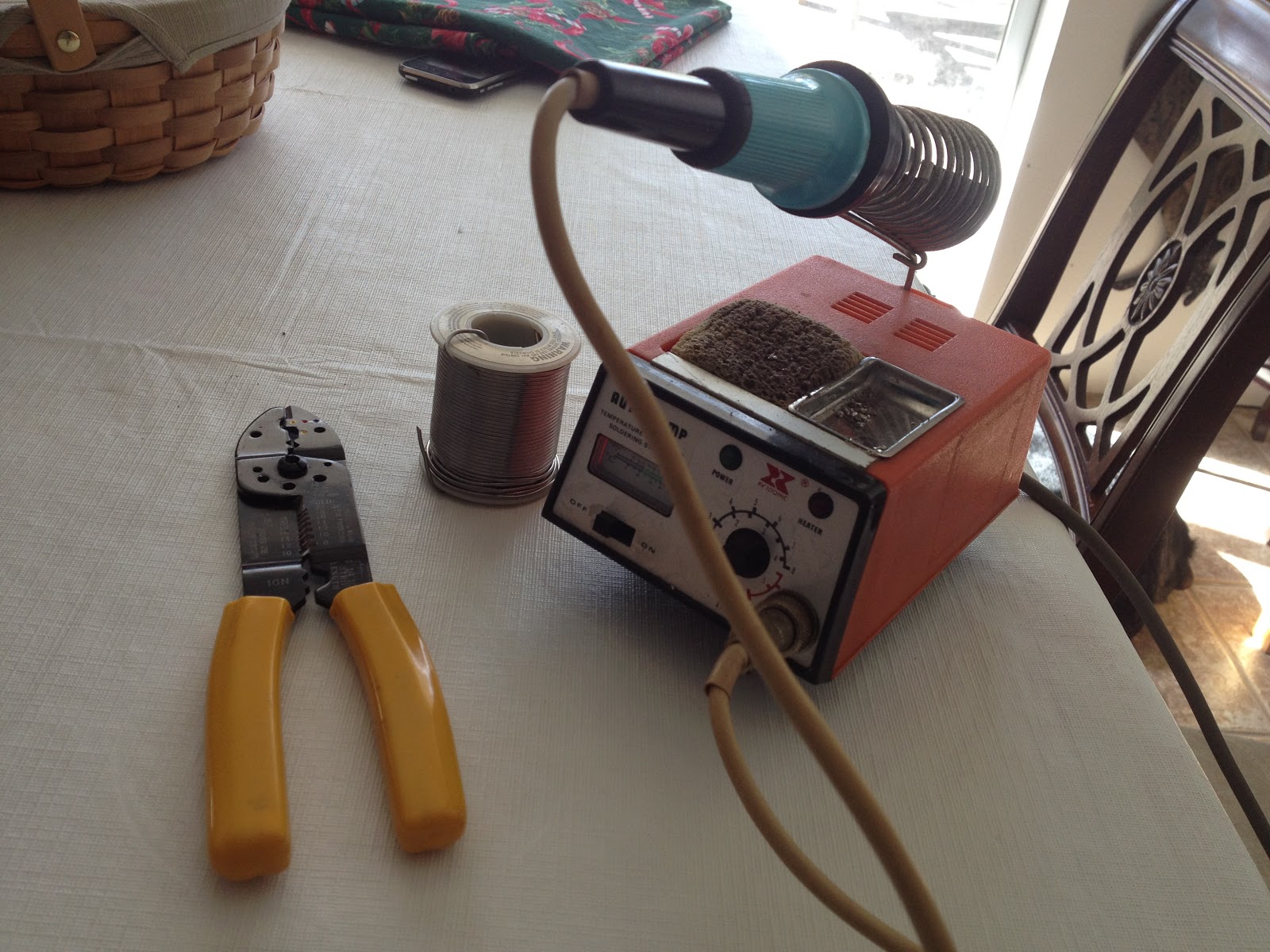


Our process was this:

  1. The kids sorted out the components into groups together (capacitors, resistors, transistors, etc).
    1. My youngest daughter, the eldest of the group at the bench, took on the task of sorting the resistors by color code, learning a bit about said code in the process.
  2. Each kid got a board, and with some help from Dad found the marked locations for each component (resistor X goes into the R1 location).
  3. They then bent the legs of the components so that they would fit into the holes in the board.
  4. As one kiddo got a part mounted, Daddy would solder it on and trim the excess off.  By then, the next kiddo would have a part mounted and the process would continue.
  5. We continued on in this vain until all of the parts were on the board (first resistors, then capacitors, then transistors, and finally LEDs).
  6. Once that was done, Daddy soldered on the battery leads and joined the two halves together with jumpers (the hardest part of the project).
All in all it was a fun little project that took about and hour and a half from start to finish, and we ended up with an ornament that we can use for many Christmases to come!  

Here is a shot of the eager little technicians that help during the build out, along with the fruit of their labors:


And a close up of the finished tree:


And a couple of shots with the lights off to show the blinking motion of the LEDs:


This was a fun little project and helped to keep the kiddos entertained while Mommy was a work!  I hope to get back to some radio related projects in the near future, like maybe that RockMite kit, or installing a 4BTV vertical, or building a 12el yagi for 2m, or a "turnstile" moxon for satellite work on field day, or you get the idea...  Maybe during some vacation time that I am planning on taking in January...  Time will tell.

Merry Christmas and Happy New Year!

73,

Richard, KK4JDO

Monday, November 12, 2012

OT: Science Project

This is way off topic, but I wanted to share a science project that I made with my 12 year old daughter last year for her 6th grade natural science class.  She was required to make a replica of a cell, whether animal or vegetable didn't matter, as long as it was accurate and labeled the components that make up a typical cell.

We decided that we wanted something that was a little more impressive than your run-of-the-mill school project made with noodles and play-dough.  So after much brainstorming and looking around hobby stores and Home Depot, we decided to go high-tech.

We constructed the cell walls out of plexiglass:
We made a cube out of six pieces of plexi, then build two spacers for inside the cube out of four more pieces.


Connected the pieces of plexi with clear packing tape:
We make sure to keep wrinkles to a minimum and used just enough tape to keep it together.


Added organelles by printing them on 8.5" x 11" labels:
We cut the shapes out using an Xacto hobby knife to be able to keep close to the lines. 


And gave it a little flash with a Sylvania LED "Light Flute":
This was a little tricky.  The hardest part was positioning it close enough to door to be able to turn it on, but not so close as to have it turn on by itself or break the plexi.  I tried cutting a hole in a sheet of plexi for the switch, but ended up breaking it, so we just pushed it up next to the "door" and left it like that.

The final result came out pretty well!  Here are a few pics of how it turned out.

With the lights in the room on:


And again with the lights off! 


We used clear labels to label the individual organelles.  This was a really fun project!  The teacher liked it so much that she kept it!!  It is on permanent display in her class room.  This is not a ham project, but it was still a lot of fun and I wanted to share.  Hopefully it gives you some ideas to use yourself.

73,

Richard, KK4JDO

Saturday, November 3, 2012

Quarter Wave Ground-Plane Scanner Antenna (and 2m ham antenna)

One of the purchases that I got via eBay is a Radio Shack PRO-2050 police/fire/etc scanner.  I've never had a scanner before, and this was a cheap way to check it out.  I didn't get a pick of it before I ended up moving it from the shack to the truck, so I nabbed a picture of the internet.  Here is what my scanner looks like for those that haven't seen one:


Of course, since I had a scanner, I needed an antenna.  I'm just getting into the whole scanner thing, so I didn't want to spend too much on the antenna since I didn't pay much for the scanner (which is several years old).  One of the cheapest and easiest antennas to build is the quarter-wave ground plane.  I had some #8 ground wire laying around, as well as an SO-239 connector, so I was off to the races.

There are several good calculators out there to help get the proper dimensions, however, the math is fairly simple:

468 divided by Frequency in MHz gives you the half-wave element length in feet.
The quotient from above divided by 2 gives you the quarter-wave element length in feet.
Take the quotient from the last problem and multiply it by 12, the product is the length of element in inches.

For example, if you want an antenna for the middle of the 2m ham band: 

(468/146) / 2 x 12 = 19.23" which roughly equals 19 1/4" (since tape measures are in fractions of an inch).

It helps if you cut it a little long to allow you to tune to your specific location.  I actually cut mine for resonance on the public services band (~150MHz) since that is what is in use in my area, however, I get acceptable performance on the 2m band as well (about 1.7:1 VSWR).

Bending the ground plane elements down to 45 degrees brings the resistance of the antenna closer to 50 Ohms.  I'm not sure how this works exactly, maybe someone could drop a post and let me know why this works.

Here is a quick pic of the completed antenna.  The ground plane elements sag a bit with they are supporting the weight of the antenna.  They are straight when the antenna is suspended properly.


I also added vertical stubs for the 440MHz band as well as the 800MHz bands.  I didn't add ground plane elements for them as I'm not sure that I would see any benefit from doing so since I have the 2m elements.  Here is a close up of the verticals.


The last thing that I did was to seal the top of the connector with some silicone caulking.  This will help to keep water out of the coax, which would degrade the metal over time.  I would have used coax-seal, but I ran out and didn't feel like spending the money on this antenna.


And the final thing that I need to do, as you can tell from the background of the picture above, is clean my work bench!  It is getting crazy in there, so hopefully I can get that squared away soon.

My Parts List:

  • 1 x SO-239 connector
  • 8' of #8 grounding wire
  • 4 x little screws
  • Caulking
Time to Completion:
  • About one hour for this one, mainly getting the jig built to solder the pieces together.

Next time I'll work on getting better pictures.  I tend to feel my way through some of these projects and don't think to document as I fumble along.

73,

Richard, KK4JDO

Sunday, July 22, 2012

Rainy afternoon project with the kids: Coax Tester!

After finishing up the souncard interface yesterday, I thought that I would be done for a few days, but a house full of boisterous kids on a rainy day dictated otherwise.  As they say, necessity is the mother of invention, or in this case, maintaining my sanity was...  ;-)

I recalled watching a YouTube video by W5CYF (Tinker John) on how to make a simple go/go-go coax tester.  It seemed like a good project for the kids and I to do.  Like John, I used a green LED to mean the coax is bad, but hey, it's what I had on hand.

This is a simple, quick and dirty schematic of what we built:


In a project list this, there are a few things that kids can do, and a few that an adult needs to do.  While watching the kids play with the drill or soldering iron would be entertaining in a scary sort of way, the trip to the hospital afterwards would have been annoying.  However, seven year olds are good at sorting resistors by color, and 9 year olds are good at tightening screws.  They are also both helpful when small parts are dropped by fumble fingered parents.  Just remember that kids are kids, and tend to be distracted and not remember the goal.  They also like to fidget A LOT.  My son got to spend a few minutes in his room due to this, but he settled down and was back for the finish and testing.

My Parts List:

  • 1 x SO-239 connector
  • 1 x 9V battery connector
  • 1 x 350 Ohm resistor
  • 1 x Green LED
  • 1 x Small project box
  • 1 x 7 year old boy
  • 1 x 9 year old girl

Time to Completion:
  • About two hours, after all, the kids were helping me!  ;-)

Here are a few pics:

Here are the two proud builders!

Picture of the tester.

In this picture, I used a small bit of solder to simulate a piece of bad shorted coax.  Notice the green LED is on.  Green usually means good, but in this case, green is NO-GO!


Again, this was a fun little project that will give you an absolute basic go/no-go test of a piece of unknown coax.  It won't tell you impedance or length, if you need those tests go get an MFJ-259B or something similar.  If you want to make sure that you don't have a dead short and won't blow up your finals, this is the tool for you.  ;-)

73,

Richard, KK4JDO


Thursday, July 12, 2012

SS-64 Encoder installation into Kenwood TR-9000

Recently I had the opportunity to purchase a pristine Kenwood TR-9000 radio.  It was manufactured in the 1980s, but looks like it just came off the showroom floor.  I love these older Kenwood radios!  So far I have a:
  • TS-440S/AT for working HF
  • TR-7730 that I use for VHF packet and APRS
  • TR-9000 all mode 2m radio that I use for weak-signal work and now local ragchews
The only drawback to the older VHF radios is a lack of ability to encode CTCSS (PL) tones.  For APRS or packet use, this isn't an issue, so my 7730 is great at what it does.  However, I really want to use my new TR-9000 to participate in local nets, in addition to (trying) to work SSB.  Since this radio doesn't have a tone encoder, I have been unable to use it on local repeaters that require a subaudible PL tones to key up.  Enter the Com-Spec SS-64 encoder board.  For a whopping $30 I was able to purchase one of these babies to add this functionality to my Kenwood!


The installation process was much simpler that I had anticipated. All that was involved was taking the case off of the radio, removing one of the sub boards, and soldering three wires.  Boom, done!  To aid anyone that may be trying to do that, I have taken some pictures of what you need to look for.

There are three leads that are of primary concern with this board, red and black for power and ground, respectively,  and yellow for modulation.  The red and black are easy enough to figure out.  I connected them to the incoming 12V lead on the back of the radio, and to the chassis ground lead in the same location.

The yellow wire is a little more complicated.  It needs to be connected at the junction of the VR-2 variable resistor, and the C-16 capacitor.  Finding these required digging through the schematics and snooping around the boards themselves.  Here is a picture of the board that you will find them on:


This board is located in the back of the radio, under the top cover.  The specific two components that you are looking for are located in the bottom left of this picture.  Here is a close up (hint: look at the brown round thing standing up, and the green thing that looks like a tic-tac right next to it):


The tricky part is that you cannot solder to this side of the board, you will need to flip it over, then locate the proper pins to connect to.  Here is a picture to help you identify the proper pins:


I forgot to take any pictures of after I had solder the connections, I was too eager to talk on my local 147.120MHz repeater!  

I routed the rest of the cables from the under side of the radio since there is more room to install the encoder board there.  I used the double sticky tape enclosed with the board to mount it next to the speaker.  According to the instructions, you may need to make some fine-tuning adjustments to the frequency by adjusting a pot on the encoder board itself, but I did not find this to be necessary.

I hope that this has helped anyone that is trying to do this installation to this radio.  It may seem complicated, but it is fairly straight-forward if you approach it methodically.  Take plenty of pictures to remind yourself what cables went where, or take good notes.  But that holds true for any project.

My Parts List:
  • 1 x Com-Spec SS-64 encoder
  • 1 x Kenwood TR-9000 2m radio

Time to Completion:
  • Approximately one hour

This was a fun little project that added a tremendous amount of functionality to my radio!  There are several more mods in this radio's future.  An extremely knowledgeable ham that I talked to on the repeater (N4LGH) has mentioned a few, and I've been reading about a few, so stay tuned!

73,

Richard, KK4JDO

Sunday, June 17, 2012

Fun Project with the Kids

Here is a fun little project to do with kids.  It is also educational.  This was done a few years ago, but we still have fun with it from time to time.  This is a simple electro-magnet built by winding some copper wire around a steel screw, and connecting it to an electrical current (low voltage provided by some "AA" batteries) via an on/off switch.  I stuck a little LED in there to show when it was turned on, not that it was needed with a switch that was labeled, but it was fun.

My Parts List:

  • 1 x Project Box
  • 1 x 6' of copper wire
  • 1 x Screw
  • 1 x SPST switch
  • 1 x LED (with resistor built in)
  • 1 x power connecter (really not needed, batteries could be inside of project box)


Time to Completion:

  • About four hours with the "help" from the kids.  ;-)


Here is a pic:


Just a fun little project.  I'll work on getting some pictures of it in use.

Thanks,

Richard, KK4JDO