Showing posts with label kenwood. Show all posts

Tuesday, May 7, 2013

Revised audio testing of the Kenwood TS-590S (now with less overdrive!)

Thanks to everyone that offered their insights into helping me get this audio test going with something close to optimal results!  In this post I will cover multiple settings side-by-side:

  • EQ Off , Speech Processor Off
  • EQ Off , Speech Processor On - Soft Effect
  • EQ Off , Speech Processor On - Hard Effect
  • EQ On , Speech Processor Off
  • EQ On , Speech Processor On - Soft Effect
  • EQ On , Speech Processor On - Hard Effect
In all of the tests the following settings were used:
  • Mic gain on the radio is set to 30
  • In the tests with the Proc enabled
    • Proc Input is 35
    • Proc Output is 30
  • On the PC side, the recording device input level is 27
I will also include four files that just showcase the effects of the hard and soft settings of the speech processor.  Two with the proc enabled, and two without (to show that it has no effect without the proc being turned on).

So, again, without further adieu, here are the samples:


EQ Off , Speech Processor Off EQ Off, Speech Processor On - Soft Effect EQ Off, Speech Processor On - Hard Effect EQ On , Speech Processor Off EQ On , Speech Processor On - Soft Effect EQ On , Speech Processor On - Hard Effect


And here are the files that are just about the Hard and Soft effect settings of the Speech Processor:


EQ Off , Speech Processor On - Soft Effect EQ Off , Speech Processor On - Hard Effect EQ Off , Speech Processor Off - Soft Effect EQ Off , Speech Processor Off - Hard Effect


Whew!  That was a fair amount of effort for a lazy fat man!  Feel free to let me know what you think, and hopefully this will help you determine what your own settings should be.  I'm starting to like conventional with the proc off for ragchews and with it on for weaker band conditions, with proc on and high boost 2 for bad conditions or DX (or maybe for the 590 net...hihi).

Hope you enjoy it and 73,

Richard, KK4JDO

Saturday, May 4, 2013

Kenwood TS-590S Audio Testing

EDIT:  The audio on this post is extremely overdriven due to incorrect recording levels on the PC.  I have updated this with the correct setting in a new post at:

http://hamprojects.blogspot.com/2013/05/revised-audio-testing-of-kenwood-ts.html


There has been a lot of discussion lately on one of the mailing lists that I subscribe to pertaining to the audio tweaking that is possible on the Kenwood TS-590S.  I am far from an audiophile, so I thought that I'd do some playing around this evening and record some test files to hear what the different default options sound like.

Thus far, I have to say that I like the sound of the rig without the EQ on for ragchews, but I think that the High Boost options are great for DX.  Take a listen and let me know which ones you think sound the best!  I tried to record each file with the same configuration as far as what I say, where the mic is, ambient noise in the room, etc.  I am currently using the stock mic, but am hoping to upgrade to the Shure SM-7b in the near future at the suggestion of a friend in the A/V world.

So, without further adieu, here are the files:

http://hamprojects.blogspot.com/2013/05/revised-audio-testing-of-kenwood-ts.html


So, if you listened to all of those files, you are quite the patient person!  Hopefully the sound of my voice wasn't too unpleasant, at least I hope it was better than sticking a rat-tail file in your ear.

On a different note, look for an upcoming post regarding the EZNEC antenna modeling program and some PERL scripts that I wrote to make it easier to do certain things in it.

With that I'll say 73 for this evening and wish you the best for you and your family and GUD DX!

73,

Richard, KK4JDO

Wednesday, April 10, 2013

Going places in the truck

So this post isn't about actually about going anywhere, instead it is about the direction that I want to go with the radios in my truck.  If you look at some older posts here you will see that I have tried a few things in the past, but I think that I am finally figuring out what I want to get in the way of radio gear in the truck.

So let's start at my current position.  Right now the only rig that I have in the truck is a Kenwood TM-710a dual-band 2m/70cm analog radio with APRS support built in:


This is an awesome radio with great receive and a lot of features.  Just like the picture above, I keep the left side tuned for APRS and use the right side for chatting/scanning.  I hope to add a Green Light Labs GPS in the near future, at which point I will enable beaconing, but it is a lot of fun watching the stations near me pop up on the screen and exchanging text messages with them.

Moving on, the next radio that I would like to add is the Kenwood TS-480SAT to get HF back in the truck.


I used to have an Icom 706MkII in there and discovered that I need at do a lot of work to get the truck RF quiet, which will be another post of series of posts.  But that doesn't change the fact that I miss having HF in there, especially on longer trips.  I want to couple this radio to a Tarheel 100A-HP antenna.


The Tarheel covers 80m through 10m without me having to get out and change a resonator tip or move a wander lead around.  I would like to either find an electronic auto tuner that enables the tune button on the 480SAT, or build one myself.  That would enable one-touch-tuning of the antenna for any band.

The next thing that I would like to add is the Icom IC-2820H to get me the ability to access 2m/70cm digital modes (D-STAR).

I'm starting to see more and more repeaters go digital and would like to be able to access them.  Plus I've been reading about a lot of fun stuff that can be done with PC integration in the D-STAR world and want to be able to play around.

Still in the D-STAR world, I would also like to add the Icom ID-1 radio.


This radio lives in the 1.2GHZ digital world, and also has the ability to do 128k data connection, which means internet access when there is a repeater that supports it near by.  You can also do 128k data simplex between two radios which opens all sorts of fun and interesting possibilities, especially for EmComm work.

Okay, still with me?

I have a few more things that I would like to add also.  One of them is a Cisco 1232AG 802.11 wireless access point.


And of course, even an AP needs an antenna, so I was thinking of getting one of the antenna below to resonate the 2.5GHz/5GHz microwaves from the AP.  If I added a high quality switch to flip the antenna between the AP and my laptop/mobile PC, I would also be able to war-drive nicely.  I could then tie in the GPS and plot open access points as I drive along, but that is a subject for another post.


An AP would let me access the data capabilities of the ID-1 from my laptop anywhere near the truck!  Of course, this AP doesn't run on 12V, so I would need a DC-DC regulator to get from 12V to the required 48V at 300mA.  I've seen several on-line, like the one below, but I think that I would prefer to build one.


So anyhow, after all of that, and about three or four thousand dollars, I would have comm gear in the truck that spans the spectrum from 3.5MHz to 5GHz.  Not quite DC to Daylight, but not bad for a civilian pick-up owned by a hobbyist.  Maybe in a future post I'll do up a Visio diagram of how it will all fit under the backseat and how the cables will route.  Then I can dream in earnest...  The plan will be all set and all that prevents its execution is, well, ya know... Money.  ;-)

With all that I will bring this lengthy post to a close.  I've been participating in the Kenwood TS-590 net on 7.235MHz as I write this.  Lotsa static, but a great net, so if you have a '590 come over on Wednesday nights at 0100z.

73,

Richard, KK4JDO

Saturday, February 16, 2013

Import TravelPlus (TPE) files into the Kenwood TS-2000

So it is probably pretty obvious that I prefer Kenwood radios.  I have made a lot of changes here in the shack, one of the coolest being that I have added some new radios!  As you probably guessed by the title of this post, one of those radios is a Kenwood TS-2000!

I also have another new radio, an absolutely awesome Kenwood TS-590S that I use for HF, so the TS-2000's main role is VHF/UHF and Satellite work.  I treat the higher bands a little differently than HF in that I use a lot of memories for local repeaters, FM calling, SSB calling, etc.  This lets me do memory scans and monitor several repeaters and simplex at the same time.

The ARRL has a great (well, okay, workable) software package called Travel Plus that tracks repeater frequencies, etc.  While I don't use the software because I feel that it is too expensive for the 1990's style programming, it does serve to help the hobby by introducing a file format standard that several of the other providers of this information have picked up and used.  I like RFinder and use it for finding repeaters in my area.  Don't get me wrong, all of these services have issues, but I think that RFinder is the best of a sad lot.  In their defense, it has got to be like herding cats trying to get hams to use the same standard for data input when adding their repeaters to the services.

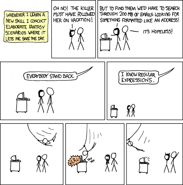
Anyhow, I wanted to import this database of repeaters into my TS-2000, only to sadly find that the MCP-2000 program offered by Kenwood doesn't allow you to import anything other than files in its own format.  Well that sucked, to put it mildly.  I was all happy to find this MCP 2000 program to begin with.  Then to have those hopes dashed...  Enter this XKCD comic:


This comic accurately describes how I feel.  Thank God I sort-of know PERL.  So let me break down how I fixed this problem, and maybe save you the trouble.

First off.  Kenwood's File Format.  Kenwood likes to use some random obscure string of numbers and letters to represent information like input frequency and offset and what mode you are using and whether or not you are using positive or negative shifts.

It looks like this:

000000147120000402081300001000600000000N4LGH

Or, a whole bunch of them:


000000147120000402081300001000600000000N4LGH
000100442450000402081300001005000000000KG4RPH
000200444950000402081900001005000000000WC4PEM
000300444900000402081300001005000000000KC4VBZ
000400444725000402081300001005000000000G4ZPZ
000500444400000402081300001005000000000W4JAZ
000600444675000402081300001005000000000WB4OEZ
000700443050000402081400001005000000000W9TT
000800443750000402081300001005000000000K4KCJ
000900443550000402081300001005000000000KD4MBN
001000443975000402081300001005000000000AG4AN
001100444100000402081800001005000000000AG4AN
001200444450000402081300001005000000000K4SLB
001300443900000402080600001005000000000N4JMY
001400444300000402081900001005000000000WP3BC
001500444550000402081300001005000000000N1KDO
001600444775000402080300001005000000000N4KEG
001700443700000402081300001005000000000KD4JYD
001800444500000402081300001005000000000KC4VBZ
001900444425000402081400001005000000000W4MLB
002000443925000402081300001005000000000K4AJM
002100443325000402081300001005000000000WD4IXD
002200442000000402081300001005000000000WD4WDW
002300442075000402081300001005000000000KC4SGG
002400442100000402081300001005000000000KE4TTE
002500442175000402081300001005000000000WR4BS

Isn't that easy to read?  Give you a warm fuzzy feeling?  Yeah, right, me neither...

So here is a break-down of what that awesome string means:

000000147120000402081300001000600000000N4LGH

MEM - First four characters are the memory position that will be used in your radio:


0000


FREQ - The next string is the frequency, padded with leading and trailing zeros, and no dot

00147120000


MODE - This next character is the mode (FM, AM, SSB, etc)

4


PL - Then the PL tone type (Tone, CTCSS, DCS)

02


TONE - Now the tone itself, as referenced in a table in the program

08


CTCSS - Then the CTCSS, also as referenced in a table in the program

13


DCS - After that is the DCS, you guessed it, it is also as referenced in a table in the program

000


REV - Then whether or not to create a reverse entry also:

0


SHIFT - Now what kind of shift to use (positive, negative, or simplex)

1


??? - Not sure about this one, it may be an additional leading zero for the frequency offset

0


OFFSET - And now the offset frequency, this represents 600kHz with a lot of leading and trailing zeros

0060000000


MB - Now it would like to know what memory bank to store this memory item in

0


CALL - And finally, the call of the repeater, or whatever you want displayed up to six characters.

N4LGH


Well now, was that fun boys and girls?  I know that I had a blast figuring it out.  Sorry if I'm snarky, that is what dredging up long unused PERL skills will do to a person...

So, how about some information on some of those more cryptic fields above?  Here you go:


Mode

  • 1 LSB
  • 2 USB
  • 3 CW
  • 4 FM
  • 5 AM
  • 6 FSK
  • 7 CW-R
  • 8 FSK-R

PL

  • 1 Tone
  • 2 CTCSS
  • 3 DCS
  • 13 LOCKOUT

Tone, CTCSS, DCS

  • Correspond to position in dropdown in MCP 2000

Mem

  • Group number (0-9)

Shift

  • 0 Simplex
  • 1 Plus Shift
  • 2 Minus Shift


So there you have a quick run down on the file format used for the TS-2000's memory manager.

Using that information, I wrote a PERL script to take a TPE file, parse it out, and output that unGodly block of numbers and text that I was able to paste into the file that MCP-2000 uses for import into the radio.  I'm not sure how to post such a file to this blog, but email me if you would like a copy and I will happily share it with you!

I hope that this has been as much fun for you to read as it has been for me to blearily type...  ;-)

73,

Richard, KK4JDO

Saturday, December 1, 2012

Ham Shack Update

Well, with the exception of finding a Kenwood SP-120 speaker, I have just about completed a station that any ham from the late 80's to early 90's would be proud to call their own!

Just to brag (or whine, depending on time of day, my mood, and your point of view) my collection contains:

HF:
Kenwood TS-440S/AT (with FM module, IC-10 kit, Voice Module, tuner, and ALL optional filters)
Kenwood PS-430 power supply
Kenwood SP-430 speaker
Kenwood AT-250 outboard tuner (for 160m)
Kenwood IF-232C computer interface
Kenwood MC-50 microphone

VHF:
Kenwood TR-9000 (with ComSpec SS-64 tone module) 2m All Mode radio
Kenwood PS-20 power supply
Kenwood SP-120 speaker
Kenwood BO-9 base shelf
Kenwood TR-7730 (2m FM for APRS)
Mirage B-34-G amplifier with GaAsFET per-amp

UHF:
Kenwood TR-9500 70cm All Mode radio
Kenwood PS-20 power supply
Kenwood BO-9A base shelf
NEED THE SPEAKER!  ;-)

MISC:
SignaLink USB soundcard interface
Homebrew soundcard interface (cost <$20 and works just as well as the Signalink)
Homebrew coax tester
Homebrew LED ambiance lights ;-)
Homebrew PTT mic to PC interface
Wouxon KG-UV3D dual-band HT
Heath bench variable power supply
Radio Shack SWR/power meter
MFJ-941D antenna tuner
Cheap CW key

MOBILE:
Yaesu FT-2900R
Galaxy DX959
Radio Shack HTX-10
Radio Shack PRO-2050 scanner
Homebrew radio console

ANTENNA:
RadioWavz G5RV Lite
Homebrew 2m moxon
Homebrew 2m 1/4 wave ground plane

While this may all seem like an impressive list of equipment, it can all be replaced with one radio these days.  The Kenwood TS-2000, the ICOM 7000, the Yaesu FT-857D will each do everything that this entire list does and take up less space and power in the process!  Plus the new radios have DSP to clean up those weak signals.  On the flip side, all of the equipment listed didn't cost me what a fully loaded TS-2000 would cost.  So, pros and cons to each approach.

Anyhow, here is a quick pic of my shack (ignore the ugly desk, its not finished, and I'm an engineer, not a skilled wood worker, although I generally enjoy trying).


So anywho, there you go.  A shadowy flight into the ham shack of a man who does not exist...  Sorry, couldn't resist the geeky Knight Rider reference.

73 and good night,

Richard, KK4JDO

Saturday, November 3, 2012

And... We're back...

To anyone that cares, sorry that I haven't posted in such a long  time.  My real job as a systems engineer at a children's hospital can get hectic at times.  On the bright side, we successfully opened a brand new, absolutely state of the art hospital in Orlando, FL.  Check it out at >here<

In addition to working some completely insane hours, I also moved from the massively over-sized house in the burbs to a marginally under-sized house in the country.  I'm into RC planes as well as Amateur Radio, so having a place with a lot more land allows me to enjoy both of my hobbies at home.  It also helps that this place is cheaper to heat and cool being that it is around 1,200 sq ft smaller that the last house.  Hopefully we'll be able to buy again in a few years.

I have had time for a few projects, mostly in the last week to two, and I have had some searches running on eBay and a few other sites (like QRZ.com).  As a result of these searches I have been able to acquire a Kenwood TR-9500 that I really wanted, as well as the matching BO-9A base and matching PS-20 power supply.  All that is left to have a complete system is the SP-120 speaker.  These occasionally show up on various sites, so I'll keep my eye peeled for it.  Here is a neat quick pic of my new rig:


The TR-9000 is on the middle shelf, left side (red freq display), and the TR-9500 is on the right side of the same shelf (green freq display).

Both of these rigs are all mode radios, so I have the ability to use single side band (SSB) in addition to CW and both narrow and wide band FM.  This is handy as some of the older satellites use SSB.  It also allows me to start dabbling in the world of VHF/UHF weak signal work, which takes place on SSB as well.  It is kind of neat to see how far you can talk on what are usually local area bands.  I am waiting on a Mirage B-108 to show up, which is an 80W amplifier that also contains a receive pre-amp to help with working low strength contacts.  One of these days I want to check out EME, or "moon-bounce", but that requires some seriously high-gain antenna arrays or even dishes (like re-tasked old satellite TV dishs, the big Ka band ones, not the little 18" DirecTV trashcan lids).

I also built a couple of quick desks since I no longer have an office.  I had to turn my "ham-shack" into a "ham-corner".  I built two identical desks out of 3/4" plywood and 1x12 whiteboard.  The main goal was to use as much vertical space as possible to maximize my storage options.  They are not quite finished yet, I still need to add trim, and build the linking section to make is a complete corner desk instead of two stand-alone desks.  Be at least I have a place to put my radios.  Here is a quick pic of the desk with my ham gear on it.  The other desk contains the gear that I use for work and is just to the left of it.  Not that anyone really cares how my shack is set up...lol...but I thought that someone might be interested in how my desk is designed.  Post a comment if you would like to see actual plans for them.  ;-)


One of the things that I am considering adding to the desks are a set of doors to hide the equipment when not in use.  I'm using the corner of my bedroom, and while I'm okay with seeing my stuff all the time, my XYL is only marginally impressed with the whole ham radio out in the open concept.  ;-)

Anyhow, I have a few other projects that I've been working on, and will work on adding those in additional posts this evening and in my "spare" time.  For now, have a good evening!

73,

Richard, KK4JDO

Sunday, August 12, 2012

Wanted: Kenwood TR-9500

As you may have surmised from an earlier post where I added an SS-64 CTCSS encoder to a 2m radio, I already own a Kenwood TR-9000.  In fact, I have the complete station which includes the radio itself, as well as the matching SP-120 speaker, PS-20 power supply, and BO-9 base "shelf".  Here is a stock picture of this setup:


This is an absolutely awesome all-mode 2m VHF radio.  It can do Wide-Band FM, Narrow-Band, USB, LSB, and CW.  With the addition of the SS-64, it can also generate CTCSS tones to access repeaters.  The radio that I'm looking for is almost identical to this one, except it has a green display and uses UHF (70cm) frequencies.  Here is a closeup that I found online of that radio:


Ideally,  I would like to get the same complete station as above.  I think that it would be awesome to have a matched set of these radios.

The reason that I'm trying to acquire the aforementioned UHF radio is that I want to get into working other stations via Amateur Radio satellites.  Operating via this mode requires you to transmit on one frequency (called the uplink frequency) and receive on a different frequency (call downlink).  So you can see why I either need two radios, or one radio that is dual-band.  I could go the dual-band route, but I have to be honest, I have fallen in love with this awesome little TR-9000 and would love to use it for this purpose as well as 2m DX and chit-chatting on local repeaters.

There are several ham radio satellites in orbit, which always serves to amaze non-hams, as well as a ham radio installation on the International Space Station.  The station on the ISS sometimes acts like the other satellites, allowing you to talk to other Earth-based operators, and sometime operates as a normal ham station, allowing you to talk to the astronauts on the station itself.  How cool is that?!

Here is a diagram of one of the amateur radio satellites currently in orbit.  It is called Delfi-C3 (DO-64).  It was launched a few years ago by the Delft University of Technology in the Netherlands as a student research project:


So, if you have one of these radios that you would like to part with at an even close to reasonable price, please let me know and maybe we can work something out!

73,

Richard, KK4JDO

Friday, August 10, 2012

Installing an IC-10 kit into a Kenwood TS-440S/AT HF Radio

I use Ham Radio Deluxe, or more specifically, Digital Master 780, for most of the digital mode communications that I do (usually just PSK31).  This software is great and does a lot of awesome stuff.  One of those cool things that you can do with HRD is rig control.  This makes it easy to jump from frequency to frequency (QSY in ham-speak) from within the software, instead of having to tune the radio and adjust the software accordingly.  It also keep your PC up-to-date on what frequency your radio is on for automated logging (really help for lazy guys like me).

Anyway, since I have an older radio, I had to modify it with an add-on kit, originally called the Kenwood IC-10 kit.  Kenwood no longer sell this kit since they made the TS-440 over 20 years ago.  However, since this kit is just basically two ICs (an 8251A and a TC4040BP), they can still be obtained.  I got mine off of eBay for $20.  This will allow 4800 baud serial communications via the ACC-1 interface on the back of the radio.

You can then use a round 6-pin DIN connector and a DB9 connector to make a serial interface cable.  Be careful as the TS-440 ACC-1 interface uses TTL voltages (5V) and serial wants to use 12V, you will either need to use Kenwood's IF-232 kit to match the voltages, or use a USB-to-serial converter with normally operates at TTL voltage levels (beware Prolific chipsets).

The install process is fairly simple, it took me around 20 minutes to complete the installation, including the time it took to take the pictures.


This is a picture of the kit itself, basically a serial UART and a CMOS timer chip.  Be sure to take static precautions, it would be a shame to do this install and have it not work due to fried ICs.  Basically, just stay at the same electrical potential as the radio and you'll be fine.  Never touch the chip without touching the radio first.  You could also use a static strap, although I generally find this to be overly cautious unless you are working with extremely sensitive parts (or extremely expensive ones).

Below is a picture of the radio that we are about to perform surgery one, to wit, a Kenwood TS-440S/AT:

Step one is to remove the top cover, which consists of eight screws (four on top, two on each side):

Be sure when you remove the top that you keep track of where the speaker cable goes so that you can put it back together when you are finished.  It is the yellow cable in this picture:

Next, flip it over and repeat the process with the bottom cover (nine screws this time, five on bottom, two on each side):

After that, remove the three screws on the bottom of the heat shield (silver part to the right with the three holes).  Also remove the four screws (two on each side) that hold the front panel in place:

Then remove the two screws that hold the top of the heat shield on:

Finally, you will be able to see the two sockets for the two ICs.  The part of the IC with the half-circle indicates the location of pin one.  This view is from the top of the radio, and pin one goes to the left:

I forgot to take a picture before I put the heat shield back on, but this is what it looks like with the IC installed.  I had to compress the pins on the ICs a bit to get them installed, which is common.  Just be careful not to bend them too much, else they may break.

Put the radio back together in the reverse order of above, and you will be off to the races!

 This is the rig control interface for HRD, you can see where I have set the frequency to the 20m PSK calling frequency:

And this is the radio after reassembly and being controlled by the PC.  The downside to this is that you cannot control the volume, nor can you get current S-level readings from the radio back into the software like you can with newer rigs.  But being able to control a 20 year old radio via the PC at all is awesome!!


Put this project together with the soundcard interface that I build in an earlier post, and you have a fully functional rig for digital modes on the ham bands!  This was a really easy and fun project and I gained a lot of useful functionality from my rig!

73,

Richard, KK4JDO

Saturday, July 21, 2012

Soundcard Interface for APRS/Packet - Part 2

Well, I finally got the PTT part of the soundcard interface working.  This was fun, and sometimes frustrating, but very educational.  I am lacking in my understanding of component level electronics engineering.  As a network engineer, I would be comfortable designing and implementing an enterprise network for a new hospital (that's a different story), but understanding why a transistor works the way it does is beyond me at this point.  So I kind of fumbled my way through this.  One thing that is very important in network engineering is attention to detail, and solid planning.  For some reason I didn't carry this over to this project, and it bit me..lol

Let me state, for the record, plan your work, and work your plan.  Don't just wing it.

Okay, on that note, on to the project.  Once again, soundcardpacket.org was a great source of information on getting this part working.  I used this schematic from their site (click on the image to see more details):


R1 = Resistor, e.g. 1K2, to reduce voltage on the IC pin 1
IC =  Integrated Circuit; this sketch shows an IC, such as a 4N33
        or PS2603 Optocoupler, which uses a Darlington pair transistor.
        (Note: to identify pin #1, look for a small embossed circle on
         the top of the IC above pin 1; or looking into the notch in one
         side of the IC with the pins down, pin #1 is to the right of the notch.)
D1 = Diode, e.g. IN4001, would shunt any potential reverse voltage
        that might damage the sensitive diode/emitter in the IC.
        (Note: the band printed on the diode marks the cathode end,
        which attaches to the Serial Port/IC Pin 1 line in the sketch above.
        The opposite/anode end attaches to Ground.)


In the last post about this project, I built the receive and transmit cables that connect the output of the radio to the input on the soundcard, and the output on the soundcard to the input on the radio.  This worked well for listening to APRS and packet conversations, but I couldn't join in without manually keying the mic, which works okay if you're doing PSK31 or other HF digital modes, but isn't as easy with packet or APRS.  With this addition, a signal is sent via the PC's comm port to key the PTT circuit on the radio.  This allows the radio to be keyed via software instead of manually.  This allows things like APRS beacons to work normally.

This particular design uses an optocoupler to isolate the radio and the PC, while still allowing communications to flow.  This, along with the audio transformers used in the last post, helps to eliminate ground loops and voltage differentials, which are a source of hum in your transmission audio.

While building my version, I found that I didn't have the required 1.2K Ohm resistor, so I substituted a 1K and a 220 Ohm resistor in series.  This took a little additional space, which was at a premium in the tiny project box that I used, but ended up working well.  As you'll recall, in the last post, I decided to build this in a project box, instead of as a set of cables.  I think that in the long run my way will be more durable since there will be less movement of the internal solder joints due to cables wiggling around.  Time will tell.

A couple of issues that I ran into:

  1. On Windows XP (need to upgrade my shack PC), the serial mouse driver keeps the RTS pin HIGH, which causes the mic to key if nothing has taken ownership of the comm port that you are using (AGWPE, Digipan, etc) to bring it LOW.
  2. The pinout of the IC that I used was different than the one pictured in the schematic, don't blindly trust any schematic, do your homework first.  It saves solder (and frustration)
  3. Don't use too small of a project box, it is easier to do things if you have the room to do them in.

A couple of lessons that I learned:
  1. When if doubt, check solder joints.
  2. Follow the voltage, step through the circuit with a multimeter and make sure that you are seeing what you expect to see.
  3. Amperage kills...  This applies to ICs and other components as well as people.
  4. Be sure that the part is installed correctly BEFORE soldering...  

My Parts List:
  • 1 x 4N33 Optoisolator
  • 1 x 1K Ohm resistor
  • 1 x 220 Ohm resistor
  • 1 x IN4001 diode
  • 2 x 1/8" mono audio jacks
  • 1 x 6-pin mic connector to interface with my TR-7730
Time to Completion:
  • This part took me about eight hours due to lack of understanding and being too trigger happy with the soldering gun.  Next time should go smoother as hopefully I have learned my lesson on this.
Here are a couple of pics:

The IC and diode on the bottom right, and the two resistors on the bottom are all that make up this part of this circuit.  The other two resistors and the two transformers are for the rx and tx circuits.  You can also see the two audio jacks that I used to connect the PC and Radio.

This shows the completed and closed project box.  Again, while I at first thought that smaller would be better, after building it, I should have used a slightly larger box.  The next one that I build will be a bit bigger.

These are the cables that I built to connect the computer to the project box, and then on to the radio.  The gray DB9 connector attaches to the comm port for RTS based PTT.  The other end of that cable is an 1/8" mono connector that attaches to the project box.  The 6-pin cable actually has two pig-tales, one 1/8" mono for audio, and another 1/8" mono for the PTT signal.


And here is a shot of the APRS terminal showing me sending and receiving traffic.  I need a better antenna to hit more than one or two stations directly, but thankfully, one of the stations that I can hit is a digipeater/IGate.


All in all this project was a lot of fun and extremely educational.  It is also a LOT cheaper than buying another SignaLink.  I think that I have around $20 invested in this, plus my time.

73,

Richard, KK4JDO

Thursday, July 12, 2012

SS-64 Encoder installation into Kenwood TR-9000

Recently I had the opportunity to purchase a pristine Kenwood TR-9000 radio.  It was manufactured in the 1980s, but looks like it just came off the showroom floor.  I love these older Kenwood radios!  So far I have a:
  • TS-440S/AT for working HF
  • TR-7730 that I use for VHF packet and APRS
  • TR-9000 all mode 2m radio that I use for weak-signal work and now local ragchews
The only drawback to the older VHF radios is a lack of ability to encode CTCSS (PL) tones.  For APRS or packet use, this isn't an issue, so my 7730 is great at what it does.  However, I really want to use my new TR-9000 to participate in local nets, in addition to (trying) to work SSB.  Since this radio doesn't have a tone encoder, I have been unable to use it on local repeaters that require a subaudible PL tones to key up.  Enter the Com-Spec SS-64 encoder board.  For a whopping $30 I was able to purchase one of these babies to add this functionality to my Kenwood!


The installation process was much simpler that I had anticipated. All that was involved was taking the case off of the radio, removing one of the sub boards, and soldering three wires.  Boom, done!  To aid anyone that may be trying to do that, I have taken some pictures of what you need to look for.

There are three leads that are of primary concern with this board, red and black for power and ground, respectively,  and yellow for modulation.  The red and black are easy enough to figure out.  I connected them to the incoming 12V lead on the back of the radio, and to the chassis ground lead in the same location.

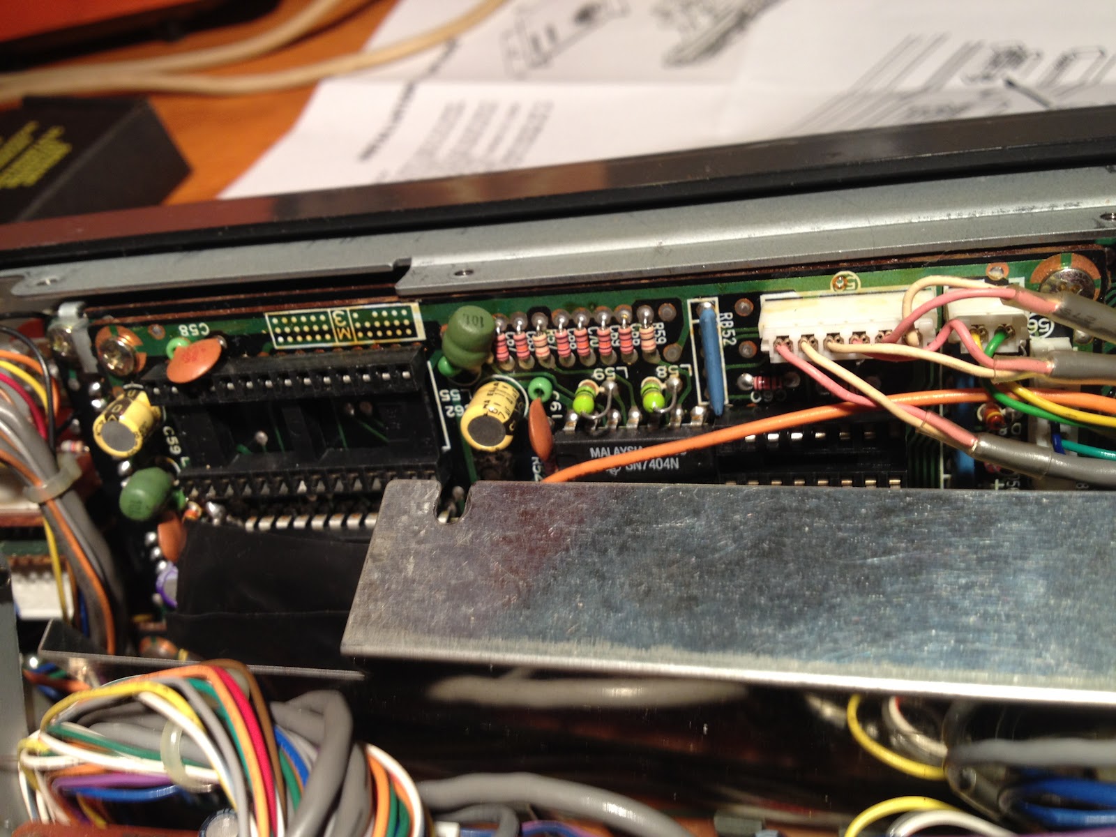
The yellow wire is a little more complicated.  It needs to be connected at the junction of the VR-2 variable resistor, and the C-16 capacitor.  Finding these required digging through the schematics and snooping around the boards themselves.  Here is a picture of the board that you will find them on:


This board is located in the back of the radio, under the top cover.  The specific two components that you are looking for are located in the bottom left of this picture.  Here is a close up (hint: look at the brown round thing standing up, and the green thing that looks like a tic-tac right next to it):


The tricky part is that you cannot solder to this side of the board, you will need to flip it over, then locate the proper pins to connect to.  Here is a picture to help you identify the proper pins:


I forgot to take any pictures of after I had solder the connections, I was too eager to talk on my local 147.120MHz repeater!  

I routed the rest of the cables from the under side of the radio since there is more room to install the encoder board there.  I used the double sticky tape enclosed with the board to mount it next to the speaker.  According to the instructions, you may need to make some fine-tuning adjustments to the frequency by adjusting a pot on the encoder board itself, but I did not find this to be necessary.

I hope that this has helped anyone that is trying to do this installation to this radio.  It may seem complicated, but it is fairly straight-forward if you approach it methodically.  Take plenty of pictures to remind yourself what cables went where, or take good notes.  But that holds true for any project.

My Parts List:
  • 1 x Com-Spec SS-64 encoder
  • 1 x Kenwood TR-9000 2m radio

Time to Completion:
  • Approximately one hour

This was a fun little project that added a tremendous amount of functionality to my radio!  There are several more mods in this radio's future.  An extremely knowledgeable ham that I talked to on the repeater (N4LGH) has mentioned a few, and I've been reading about a few, so stay tuned!

73,

Richard, KK4JDO

Wednesday, July 4, 2012

Soundcard Interface for APRS/Packet

Happy 4th of July to all of my American visitors (and also to everyone else, although I don't imagine that it is quite the same).  Not that I have that many visitors from anywhere, but it's the thought that counts.  It's been a few days since I posted anything, so I wanted to get this up on the site.  I've been enjoying my SignaLink USB soundcard interface for digital modes on HF, but I would like to run APRS on the same PC, and running two SignaLinks with APRS can be problematic.  Besides that, I didn't want to spend another $70 to $100.  So I decided to build my own interface.  There is a great resource for this at: http://www.soundcardpacket.org/.  They walk you through the build options and troubleshooting if needed.  That being said, I've borrowed their schematics to post here (full credit for the schematics goes to them).

For this interface, you will need three connections, one for receive, one for transmit and one to activate the PTT switch on your radio to allow the transmission.  I am 2/3 of the way there.  I have the send/receive portions complete, and am waiting on the parts for the PTT circuit (it requires an opto-isolator, which I couldn't get from Radio Shack).

I tested the receive and transmit using DM780, which is part of the Ham Radio Deluxe suite, and was able have a QSO via PSK31 on 14.070MHz (manually keying the mic, which is annoying).  That being said, it seems to work well, and hopefully the parts will be in soon for the PTT portion.

Here is the schematic for the receive cable.  The radio that I am using (old Kenwood TR-7730) does not support audio out via the MIC at line-level, so I opted for the 1000:8 transformer to allow me to use the speaker out jack on the back of the radio:


And here is the schematic for the transmit cable:


These are fairly basic circuits and do not require a lot of time or effort to build out.

My Parts List:

  • 1 x 1:1 audio transformer (transmit cable - RS Part #274-1374 - these are getting scarce)
  • 1 x 1000:8 audio transformer (receive cable - RS Part #274-1380)
  • 1 x 100K Resistor
  • 1 x 1K Resistor
  • 2 x mono audio jack
  • 2 x stereo audio jack
Time to Completion:
  • This one took a few hours to put together, but quite a bit of time finding the right transformer.
Here are some pics:
(I nabbed the TR-7730 pic off of the net, but it looks identical to mine)


I decided to build this out as a stand-alone box with audio jacks instead of as a set of cables for neatness.  I'm an engineer by trade, and am rather stuffy about how wiring looks.  Stay tuned for the next installment in this post when I get the parts in the complete the PTT circuitry. 

73,

Richard, KK4JDO
Sunday, June 17, 2012

Mic Adapter

I was recently in a position where I had a 2m radio that needed a new mic.  Specifically, I have a Yaesu FT-2200 that I picked up from eBay on the cheap.  This supposedly perfectly working radio had a myriad of issues, one of which being a mic with two bad capacitors.  One solution was to go purchase a new mic.  Well, this is an older radio, so they don't make mics specifically for this rig any longer.  However, I was able to find a suitable replacement, the only down side being that said replacement cost almost as much as I paid for the radio!  That wasn't gonna happen.  Another option was to rewire a mic that I already own to use with this radio.  The downside was that I actively use both mics, one for my Kenwood TS-440S, and the other (wired for the Kenwood), I use via my USB PTT box with EchoLink.  So I didn't really want to rewire either of those.

The final solution was a mic adapter!  It was a little aggravating to build as I had to cross between two vendors that do things slightly different (Kenwood uses two grounds, one for the mic, one for the PTT, while Yaesu uses a single common ground).  But it wasn't really all that bad, and seems to work.  Now I just need to get my Moxon mounted where I can use it, and I can talk on my preferred repeater without being all scratchy!

My Parts List:

  • 1 x 8-pin female mic connector
  • 1 x 8-pin male mic connector
  • 1 x 1' length of mic cable (initially I used Cat-5e, which worked good also)
  • 1 x 3" length of 1/2" PVC
  • 1 x 1/2" PVC cap


Time to Completion:

  • It took around 30 minutes to make, including scrounging the PVC to hold the male side of the connection since I didn't have a non-chassis mount connector handy.


Here is a pic:


This was an easy project that was a quick fix for a problem, and certainly cheaper than buying a new mic!

73,

Richard, KK4JDO

Monday, June 11, 2012

The Obligatory Shack Pic

So now I can show you what all of those antenna are used with!  This is a quick overall shot of my "shack" as it stands right now.  I am considering some upgrade options in the near future, so stay tuned to see what kind of rig takes center stage (thinking TS-2000 for the shack and IC-7000 or FT-857D for the truck).


Included in this pic are:

Kenwood TS-440S, 20 years old and still talking around the world!  (just talked to Russia and Ukraine!)
Yaesu FT-2200 (look for an upcoming post on lessons learned about eBay)
MFJ-941D Antenna Tuner
Heath 3A power supply for testing purposes
Kenwood PS-30 for powering the TS-440S
SignaLink USB for APRS and other digital modes (trying to talk to the ISS, but need higher gain antenna)
Wouxun UV3D HT
Kenwood TS-120S (not feeling so well these days)
Homebrew PTT Mic to USB adapter to allow me to use my desk-mic with EchoLink (look for a future post)
Shure 256T desk mic
Kenwood MC-50 desk mic
El-cheapo CW straight-key (again, look for an upcoming post)
Radio Shack SWR/Power meter


Here are some more pics:


So that sums up my current shack.  More details as things change!

73,

Richard, KK4JDO