I'm working towards the eQSL.cc eWAS award. If you're reading this you are probably already familiar with the WAS type awards, but on the off chance that you are not, WAS means "Worked All States" and the award is a certificate or plaque that you get if you have confirmed communications with all 50 US states. In the case of eQSL, the communication needs to be with someone that has AG status. This means that someone from QSL.cc has verified that they are who they say they are in order to stop cheating.
All that leads up to this. I was sitting at my rig calling CQ trying to contact some specific states when this appeared on my waterfall display:
Two stations, one at 725Hz and one at 1460Hz that collectively spread across two thirds of the available waterfall. I've looked into why this happens, and it seems that this occurs when someone pushes their rig into a non-linear state. This can be done several ways, but the usual culprit appears to be either using voice processing and ALC, having the volume output of your soundcard set too high, or trying to push too much power for the given mode. Given that PSK is a 100% duty cycle mode, some radios splatter when they are push too hard, in most cases that I've read about anything above about 40% power output pushed the rig into a non-linear state. I'm a little fuzzy on what that means exactly, but I'm doing my best to figure it out.
That was all said to lead up to this. If you ever see me on the waterfall, please send me a screenshot of what my signal looks like! Hopefully it will be a nice pretty signal since I run around 40W, don't use "PROC", and have the audio output ratcheted down so that the ALC doesn't kick in!
That oughta be about enough ramblings for this evening.
73,
Richard, KK4JDO
Showing posts with label digital. Show all posts
Thursday, March 21, 2013
Wednesday, January 2, 2013
Ham Radio can just look cool sometimes...
I had to switch out my PC in the shack, the old laptop just wasn't cutting it anymore. Not that I was able to get a new PC, but I re-purposed one of two servers that I used to run networking labs at home. I also swapped the monitors around a bit. Since I was rebuilding my PC I decided to completely revisit DM780 and actually get it all setup properly instead of just limping along without macros. I wanted to share a screenshot of it that I took last night, just because it looks cool:
I've made a few minor changes since I took the screenshot, but this is mostly what I'm using for digital modes right now. It is so handy finally having macros set up, as well as being able to easily log the contacts and upload them to LoTW and eQSL.cc. If you work PSK, give me a shout on 14.070MHz sometime!
On that note, I saw something this morning on the SuperSweeper tab that has me confused. I noticed a station calling CQ in two places on the waterfall at the same time! Here is a shot of it:
And a close up:
If anyone out there knows how this happens, please drop me a line or post a comment!
73,
Richard, KK4JDO
I've made a few minor changes since I took the screenshot, but this is mostly what I'm using for digital modes right now. It is so handy finally having macros set up, as well as being able to easily log the contacts and upload them to LoTW and eQSL.cc. If you work PSK, give me a shout on 14.070MHz sometime!
On that note, I saw something this morning on the SuperSweeper tab that has me confused. I noticed a station calling CQ in two places on the waterfall at the same time! Here is a shot of it:
And a close up:
If anyone out there knows how this happens, please drop me a line or post a comment!
73,
Richard, KK4JDO
Friday, August 10, 2012
Installing an IC-10 kit into a Kenwood TS-440S/AT HF Radio
I use Ham Radio Deluxe, or more specifically, Digital Master 780, for most of the digital mode communications that I do (usually just PSK31). This software is great and does a lot of awesome stuff. One of those cool things that you can do with HRD is rig control. This makes it easy to jump from frequency to frequency (QSY in ham-speak) from within the software, instead of having to tune the radio and adjust the software accordingly. It also keep your PC up-to-date on what frequency your radio is on for automated logging (really help for lazy guys like me).
Anyway, since I have an older radio, I had to modify it with an add-on kit, originally called the Kenwood IC-10 kit. Kenwood no longer sell this kit since they made the TS-440 over 20 years ago. However, since this kit is just basically two ICs (an 8251A and a TC4040BP), they can still be obtained. I got mine off of eBay for $20. This will allow 4800 baud serial communications via the ACC-1 interface on the back of the radio.
You can then use a round 6-pin DIN connector and a DB9 connector to make a serial interface cable. Be careful as the TS-440 ACC-1 interface uses TTL voltages (5V) and serial wants to use 12V, you will either need to use Kenwood's IF-232 kit to match the voltages, or use a USB-to-serial converter with normally operates at TTL voltage levels (beware Prolific chipsets).
The install process is fairly simple, it took me around 20 minutes to complete the installation, including the time it took to take the pictures.
This is a picture of the kit itself, basically a serial UART and a CMOS timer chip. Be sure to take static precautions, it would be a shame to do this install and have it not work due to fried ICs. Basically, just stay at the same electrical potential as the radio and you'll be fine. Never touch the chip without touching the radio first. You could also use a static strap, although I generally find this to be overly cautious unless you are working with extremely sensitive parts (or extremely expensive ones).
Below is a picture of the radio that we are about to perform surgery one, to wit, a Kenwood TS-440S/AT:
Step one is to remove the top cover, which consists of eight screws (four on top, two on each side):
Be sure when you remove the top that you keep track of where the speaker cable goes so that you can put it back together when you are finished. It is the yellow cable in this picture:
Next, flip it over and repeat the process with the bottom cover (nine screws this time, five on bottom, two on each side):
After that, remove the three screws on the bottom of the heat shield (silver part to the right with the three holes). Also remove the four screws (two on each side) that hold the front panel in place:
Then remove the two screws that hold the top of the heat shield on:
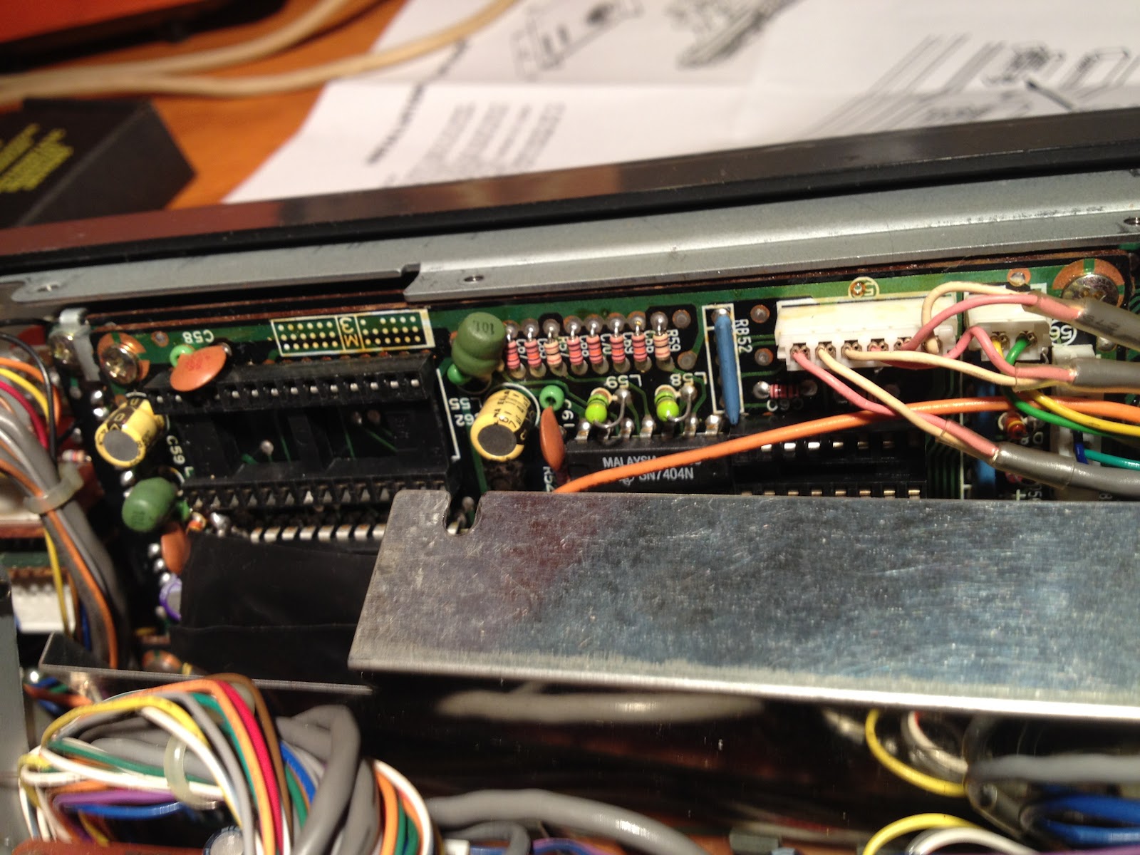
Finally, you will be able to see the two sockets for the two ICs. The part of the IC with the half-circle indicates the location of pin one. This view is from the top of the radio, and pin one goes to the left:
I forgot to take a picture before I put the heat shield back on, but this is what it looks like with the IC installed. I had to compress the pins on the ICs a bit to get them installed, which is common. Just be careful not to bend them too much, else they may break.
Put the radio back together in the reverse order of above, and you will be off to the races!
This is the rig control interface for HRD, you can see where I have set the frequency to the 20m PSK calling frequency:
And this is the radio after reassembly and being controlled by the PC. The downside to this is that you cannot control the volume, nor can you get current S-level readings from the radio back into the software like you can with newer rigs. But being able to control a 20 year old radio via the PC at all is awesome!!
Put this project together with the soundcard interface that I build in an earlier post, and you have a fully functional rig for digital modes on the ham bands! This was a really easy and fun project and I gained a lot of useful functionality from my rig!
73,
Richard, KK4JDO
Anyway, since I have an older radio, I had to modify it with an add-on kit, originally called the Kenwood IC-10 kit. Kenwood no longer sell this kit since they made the TS-440 over 20 years ago. However, since this kit is just basically two ICs (an 8251A and a TC4040BP), they can still be obtained. I got mine off of eBay for $20. This will allow 4800 baud serial communications via the ACC-1 interface on the back of the radio.
You can then use a round 6-pin DIN connector and a DB9 connector to make a serial interface cable. Be careful as the TS-440 ACC-1 interface uses TTL voltages (5V) and serial wants to use 12V, you will either need to use Kenwood's IF-232 kit to match the voltages, or use a USB-to-serial converter with normally operates at TTL voltage levels (beware Prolific chipsets).
The install process is fairly simple, it took me around 20 minutes to complete the installation, including the time it took to take the pictures.
This is a picture of the kit itself, basically a serial UART and a CMOS timer chip. Be sure to take static precautions, it would be a shame to do this install and have it not work due to fried ICs. Basically, just stay at the same electrical potential as the radio and you'll be fine. Never touch the chip without touching the radio first. You could also use a static strap, although I generally find this to be overly cautious unless you are working with extremely sensitive parts (or extremely expensive ones).
Below is a picture of the radio that we are about to perform surgery one, to wit, a Kenwood TS-440S/AT:
Step one is to remove the top cover, which consists of eight screws (four on top, two on each side):
Be sure when you remove the top that you keep track of where the speaker cable goes so that you can put it back together when you are finished. It is the yellow cable in this picture:
Next, flip it over and repeat the process with the bottom cover (nine screws this time, five on bottom, two on each side):
After that, remove the three screws on the bottom of the heat shield (silver part to the right with the three holes). Also remove the four screws (two on each side) that hold the front panel in place:
Then remove the two screws that hold the top of the heat shield on:
Finally, you will be able to see the two sockets for the two ICs. The part of the IC with the half-circle indicates the location of pin one. This view is from the top of the radio, and pin one goes to the left:
I forgot to take a picture before I put the heat shield back on, but this is what it looks like with the IC installed. I had to compress the pins on the ICs a bit to get them installed, which is common. Just be careful not to bend them too much, else they may break.
Put the radio back together in the reverse order of above, and you will be off to the races!
And this is the radio after reassembly and being controlled by the PC. The downside to this is that you cannot control the volume, nor can you get current S-level readings from the radio back into the software like you can with newer rigs. But being able to control a 20 year old radio via the PC at all is awesome!!
Put this project together with the soundcard interface that I build in an earlier post, and you have a fully functional rig for digital modes on the ham bands! This was a really easy and fun project and I gained a lot of useful functionality from my rig!
73,
Richard, KK4JDO
Subscribe to:
Posts (Atom)